EN

N Connector vs SMA Connector: Which Interface Fits Your RF Project
Choosing an RF interface is not simply a matter of picking the smallest connector that fits the enclosure. An SMA connector and a type N connector are both threaded coaxial interfaces, yet they solve different engineering problems. The better choice depends on your operating band, cable size, exposure to weather, mating cycle expectations, and the point in the system where the connection sits.
For design engineers and buyers building telecom equipment, antenna feeds, test assemblies, or embedded radio modules, this comparison turns the decision into a repeatable checklist. Rather than treating frequency as the only criterion, evaluate electrical performance and mechanical conditions together.
The practical difference between an SMA connector and a type N connector
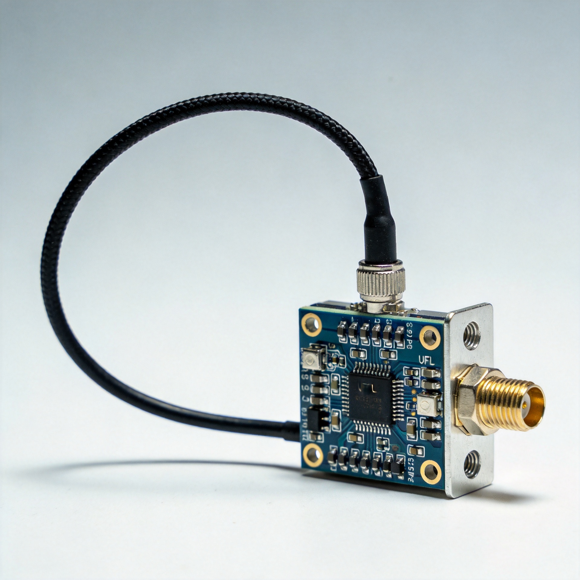
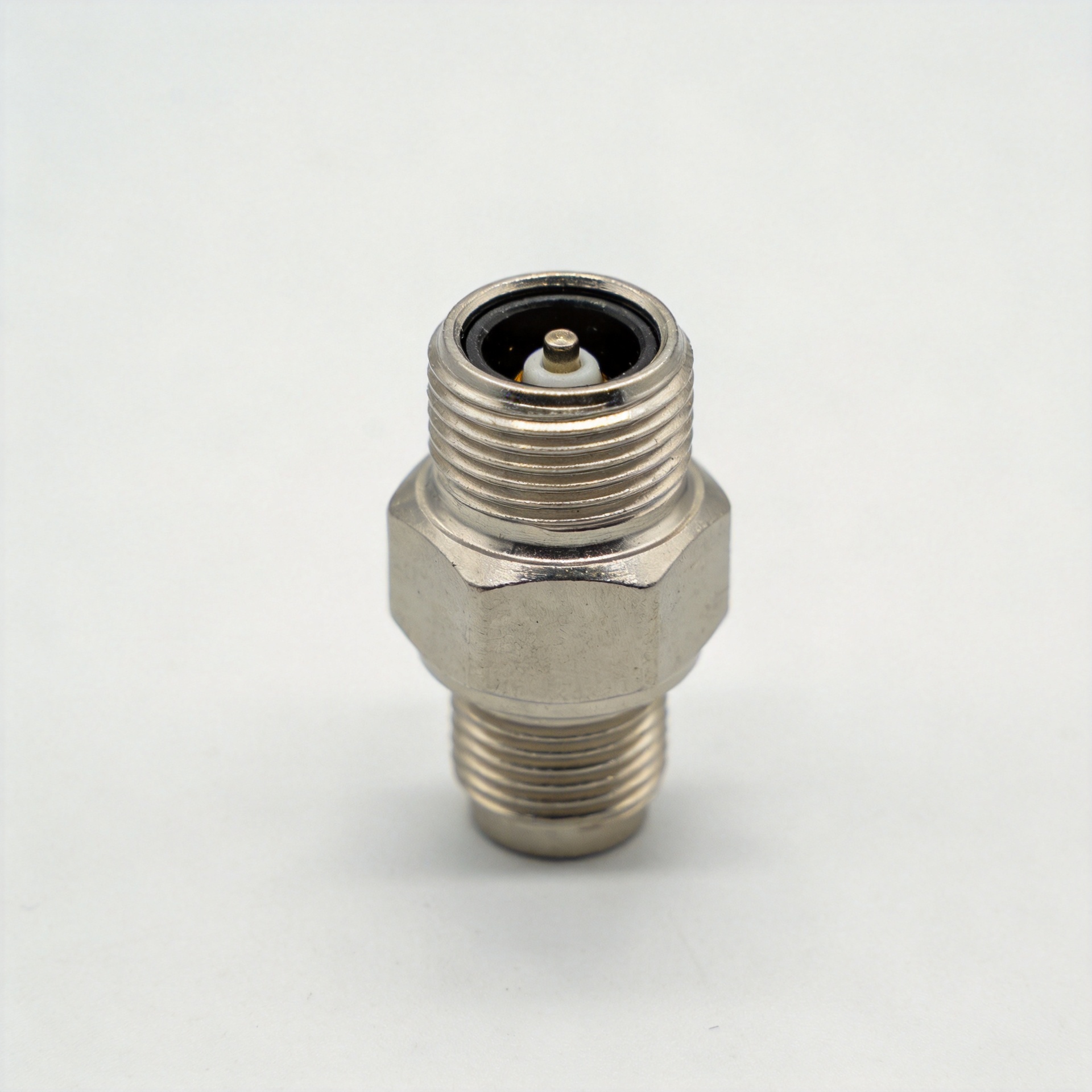
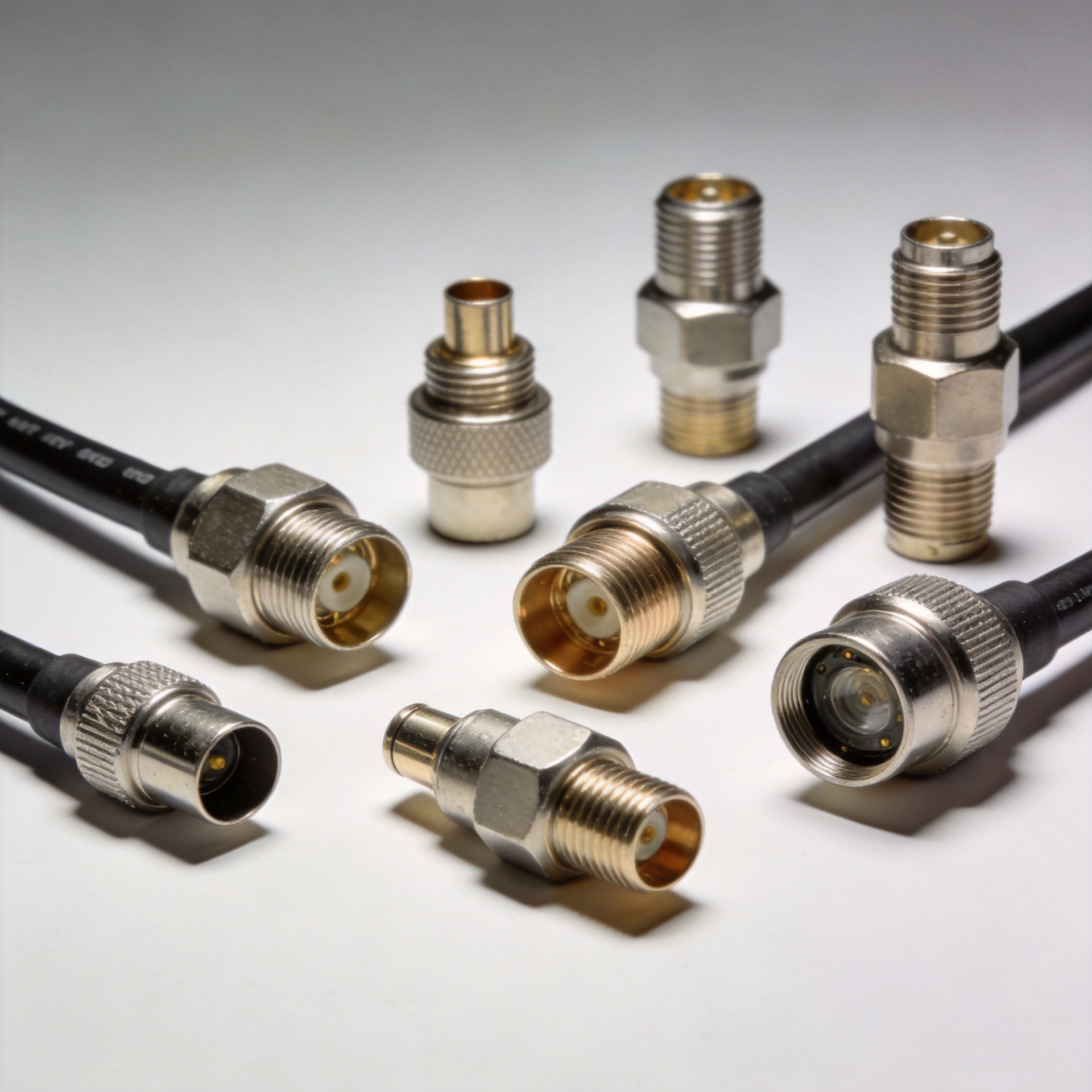
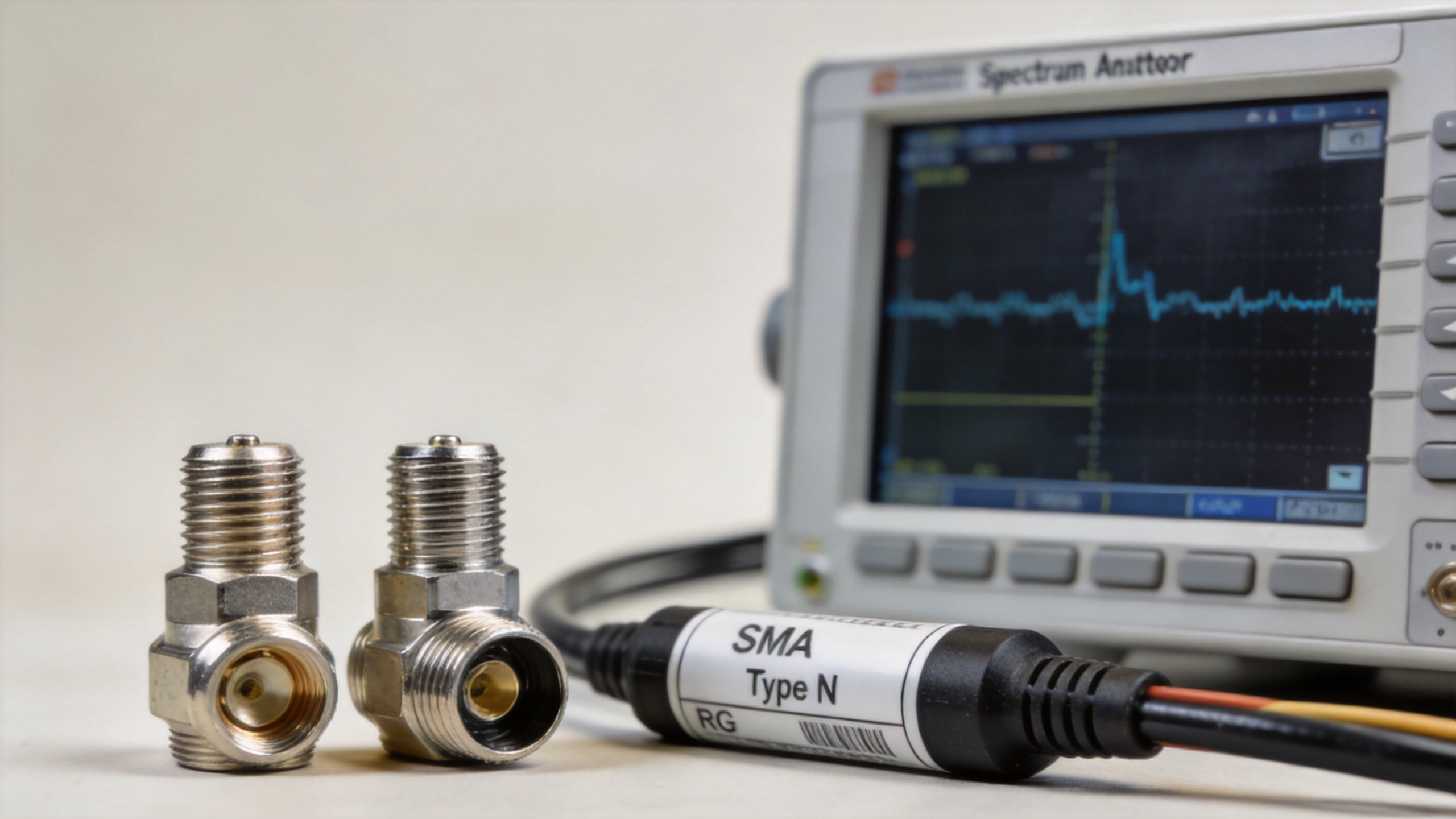
An SMA connector is a compact, threaded, 50-ohm RF connector commonly used where board space, cable diameter, and higher-frequency performance matter. It is familiar on radio modules, measurement equipment, GPS and cellular assemblies, compact antennas, and semi-rigid or flexible cable assemblies.
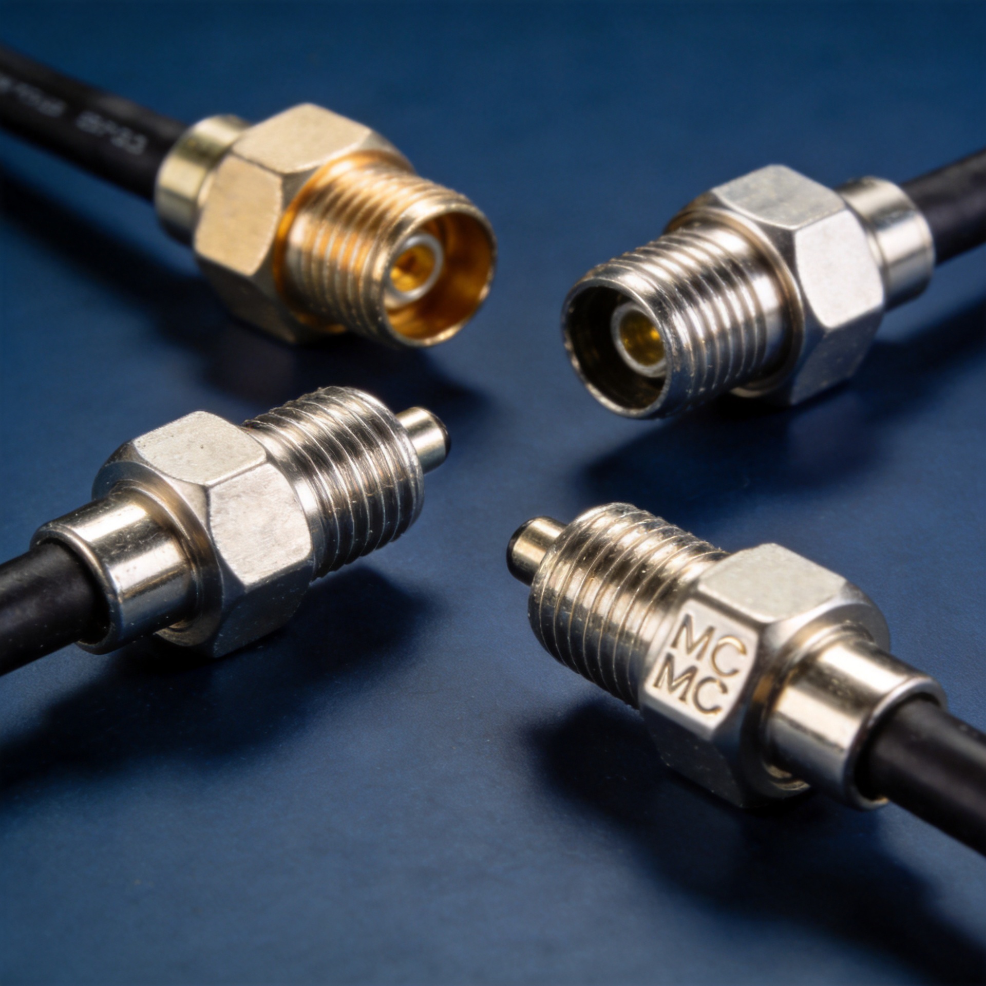
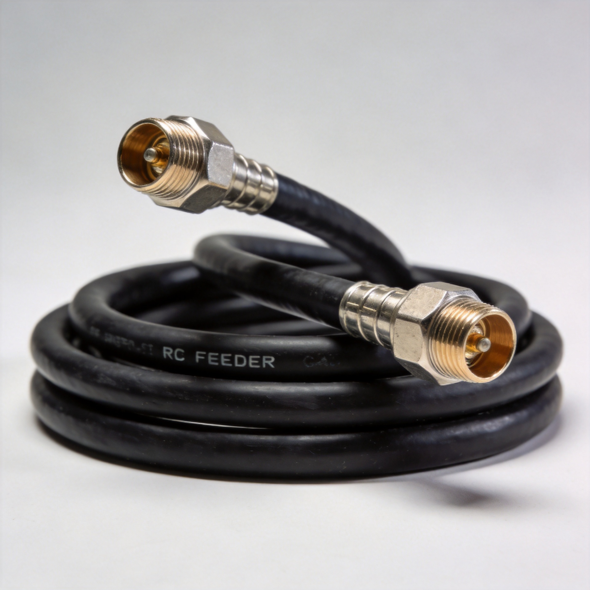
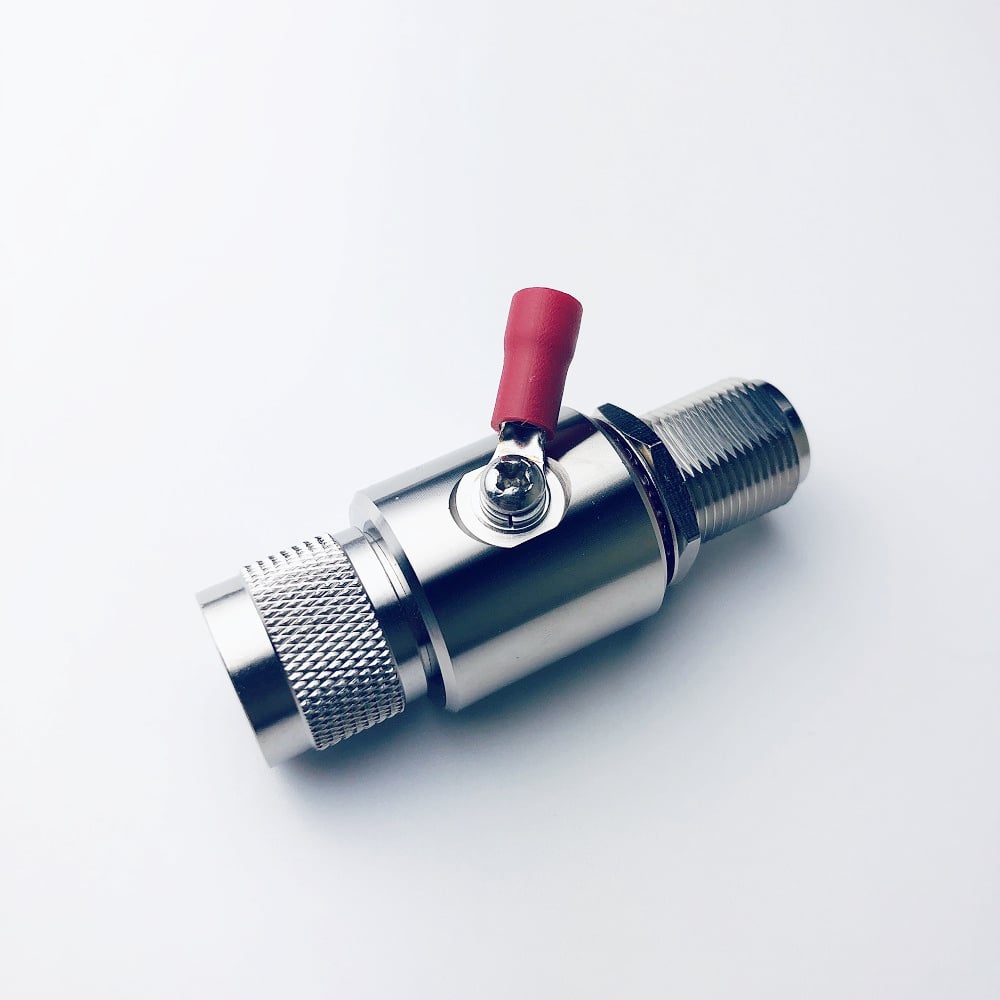
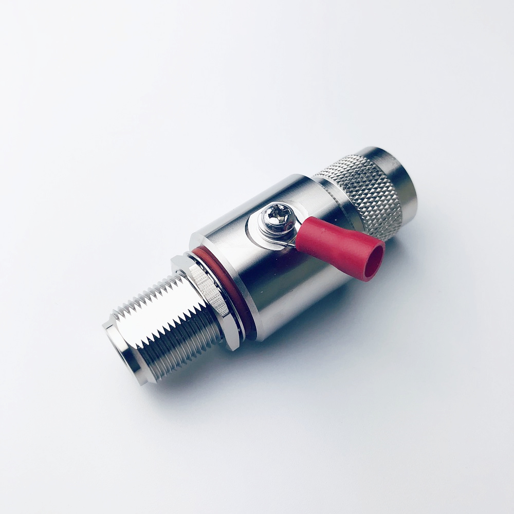
A type N connector is a larger threaded coaxial interface designed for robust field connections. It is widely used in antenna systems, feeder lines, base-station infrastructure, outdoor RF links, and laboratory installations that use larger cables. Many type N designs are built for environmental resilience; however, the actual sealing, plating, frequency rating, and cable compatibility must be verified on the selected part.
Both interfaces are available in 50-ohm RF versions. A crucial procurement detail is that N-type families also include 75-ohm variants. Do not assume an N connector is automatically appropriate for a 50-ohm RF path: verify impedance, gender, interface family, and the manufacturer drawing before releasing a BOM.
Frequency range: start with the product rating, not the family name
Frequency is often the first filter. Standard SMA connector designs are commonly specified from DC to 18 GHz, while precision versions can extend to 34 GHz. Standard N-type designs are commonly rated from DC to 11 GHz, with extended-range versions reaching 18 GHz. These figures are useful starting points, not universal guarantees. Connector geometry, cable type, assembly quality, adapter count, and test method affect the usable performance of a real RF path.
If your design operates above the usual range for a conventional N interface, an SMA connector may be the more practical baseline—provided the mechanical environment is controlled. For a lower-frequency feeder run or a rugged antenna connection, a type N connector may provide the more suitable physical interface. In both cases, compare the data-sheet limits for frequency, VSWR, insertion loss, torque, and temperature rather than relying on a catalog family label.
Size, cable compatibility, and installation conditions
| Selection factor | SMA connector | Type N connector |
|---|---|---|
| Physical scale | Compact; useful for dense equipment and small cables | Medium-size; better suited to larger cable and robust hardware |
| Typical focus | High-frequency modules, instruments, compact RF assemblies | Antennas, feeder systems, outdoor and infrastructure links |
| Coupling style | Threaded coupling requiring controlled handling | Threaded coupling with a larger, more field-oriented format |
| Environmental approach | Usually selected for protected equipment environments | Often selected when a weather-resistant interface is required |
| Important check | Confirm exact series and mating compatibility | Confirm 50-ohm versus 75-ohm version and sealing details |
For installation teams, the cable often decides the interface before the schematic does. An SMA connector supports compact cable routing and lightweight assemblies, but it is not a substitute for a larger, mechanically robust feeder interface. A type N connector offers a more substantial coupling arrangement for common feeder and antenna-side cable sizes. Select the termination style—crimp, clamp, solder, or other approved construction—only after confirming the cable’s dielectric, outer conductor, and diameter against the connector specification.
When an SMA connector is the better fit
Choose an SMA connector when the RF project needs a compact, threaded 50-ohm interface and its frequency requirements favor the SMA family. It is particularly useful for equipment panels, RF modules, test ports, embedded radios, and short interconnects where enclosure space is limited. Its small form factor also makes it practical when multiple RF channels share a dense front panel or PCB-to-cable transition.
There is a handling trade-off. SMA threads and center contacts require clean mating practices and correct torque. Frequent assembly by untrained personnel, side-loaded cables, or adapters of uncertain quality can compromise repeatability. Build a controlled mating procedure into manufacturing and service instructions, and specify the exact interface rather than using “SMA-type” as a loose description.
When a type N connector is the better fit
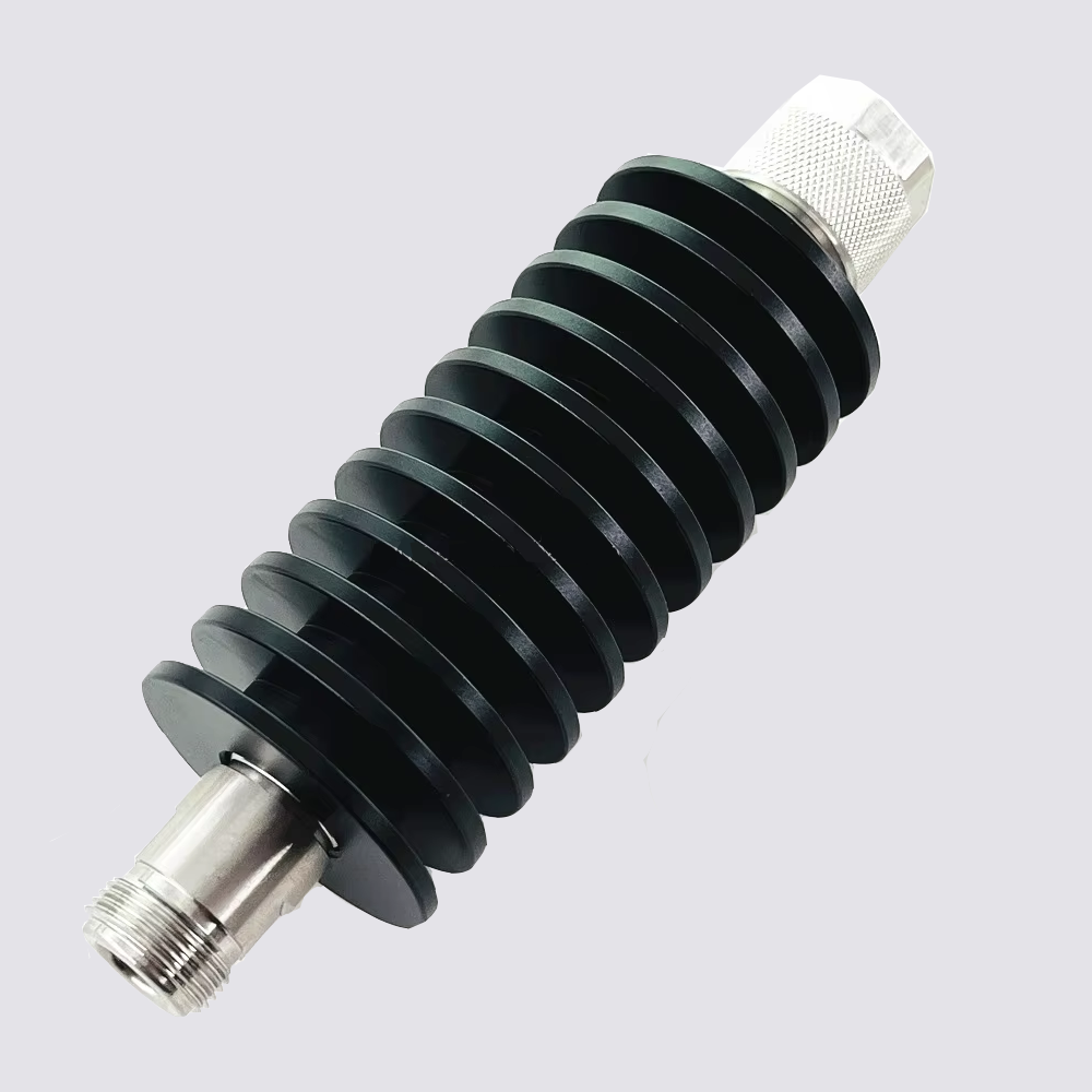
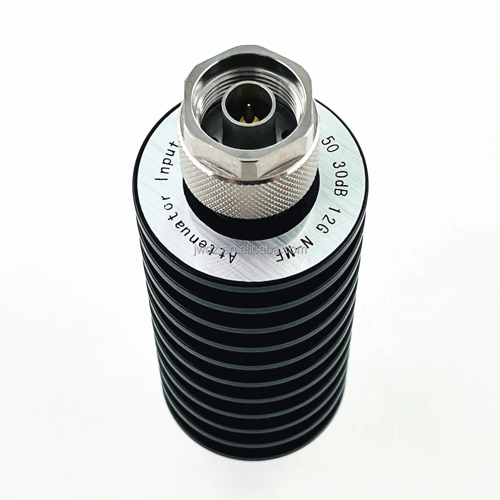
Choose a type N connector when the RF connection must tolerate a more demanding installation environment, use a larger feeder cable, or serve as an antenna-side interface. It is a strong candidate for telecom cabinets, distributed antenna systems, outdoor links, RF loads, and field serviceable cable assemblies. The larger interface is easier to identify and handle in many infrastructure settings, while its threaded coupling supports a secure connection when installed to the manufacturer’s instructions.
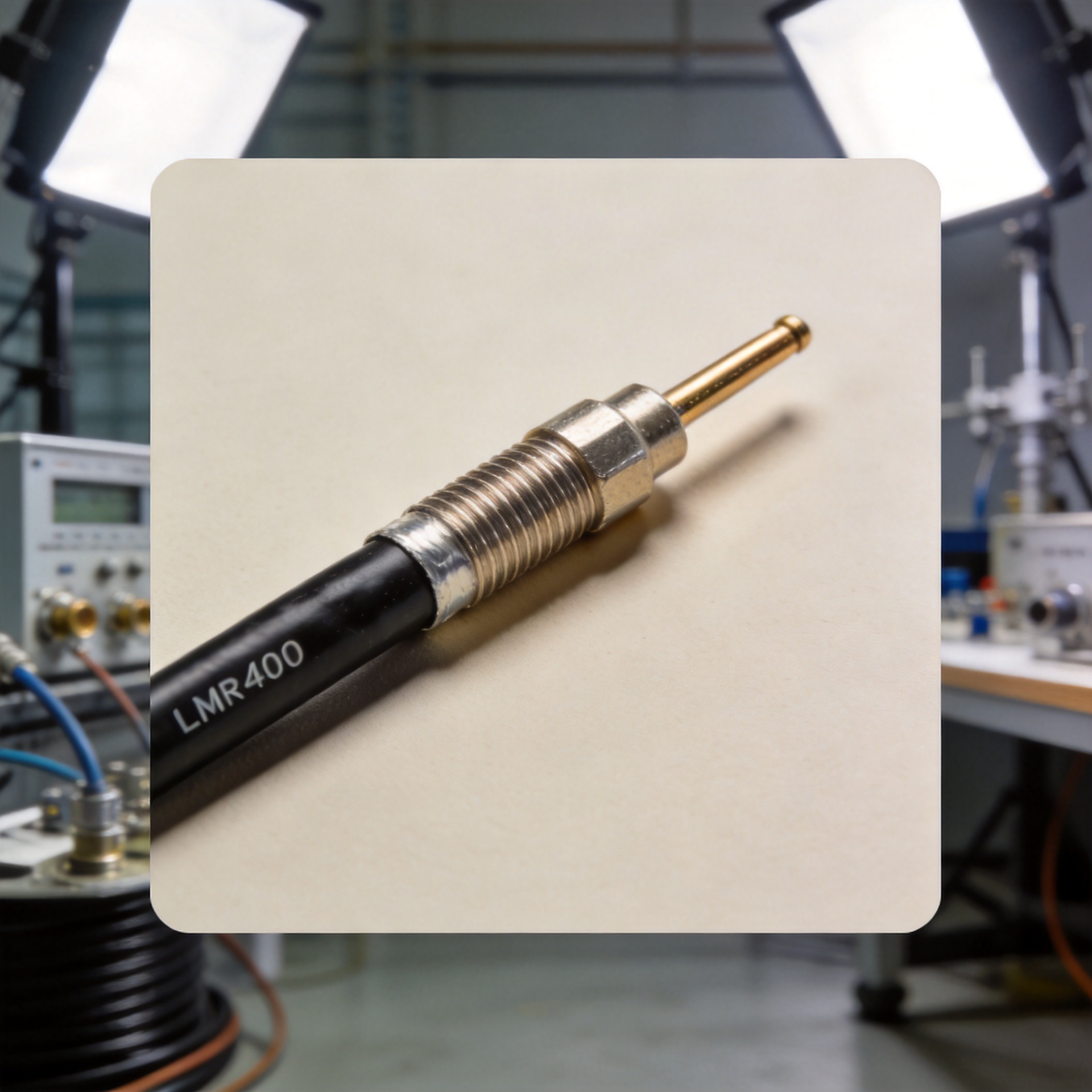
For an antenna feed or a cable run using RG58, 3D-FB, LMR195, or LMR200-class cable, review the available RF N female connector for RG58, 3D-FB, LMR195, and LMR200 cable options alongside the actual cable construction. The product title identifies compatible cable families; confirm the current product drawing and assembly requirements before specifying it for a finished system.
A five-question decision checklist
- What is the highest operating frequency? Use the full system requirement, including margin, and validate the chosen connector and cable assembly data sheet.
- Is the RF path 50 ohms or 75 ohms? Match the connector, cable, source, and load impedance. This is especially important when evaluating a type N connector.
- Where will the interface live? Protected indoor modules often favor SMA connector size; exposed antenna or feeder interfaces may favor an N-type environmental design.
- What cable must be terminated? Confirm cable diameter and construction before selecting the connector termination method.
- Who will mate and maintain it? Plan torque control, strain relief, labeling, sealing, and inspection around actual service conditions.
Common mistakes that create avoidable RF problems
The most common mistake is choosing only by frequency. A technically capable SMA connector can still be the wrong interface for a heavy outdoor feeder cable, while an N connector can be unsuitable if the project requires a frequency range beyond the selected part’s rating. Other recurring issues include mating incompatible interfaces, overlooking impedance, using unspecified adapters, failing to protect outdoor joints, and ignoring cable bend radius near the connector.
Also distinguish standard SMA from related precision or reverse-polarity variants. They may look similar enough to invite an incorrect mating assumption, but connector compatibility should be verified from the mechanical interface and data sheet, not from appearance alone.
Make the interface choice part of the RF system design
The right answer is rarely “SMA is better” or “type N is better.” An SMA connector is usually the better choice for compact, controlled, higher-frequency equipment interfaces. A type N connector is often the better choice for durable feeder, antenna, and infrastructure connections where cable size and environmental exposure carry more weight. Start with impedance and frequency, then evaluate cable, enclosure, weather sealing, service access, and installation process as a single design decision.
For RF connector and cable-assembly sourcing, document the complete interface definition: gender, impedance, coupling style, cable type, frequency requirement, environmental conditions, and verification method. That level of detail helps engineering, purchasing, and production select the same interface—and reduces rework after the first RF test.