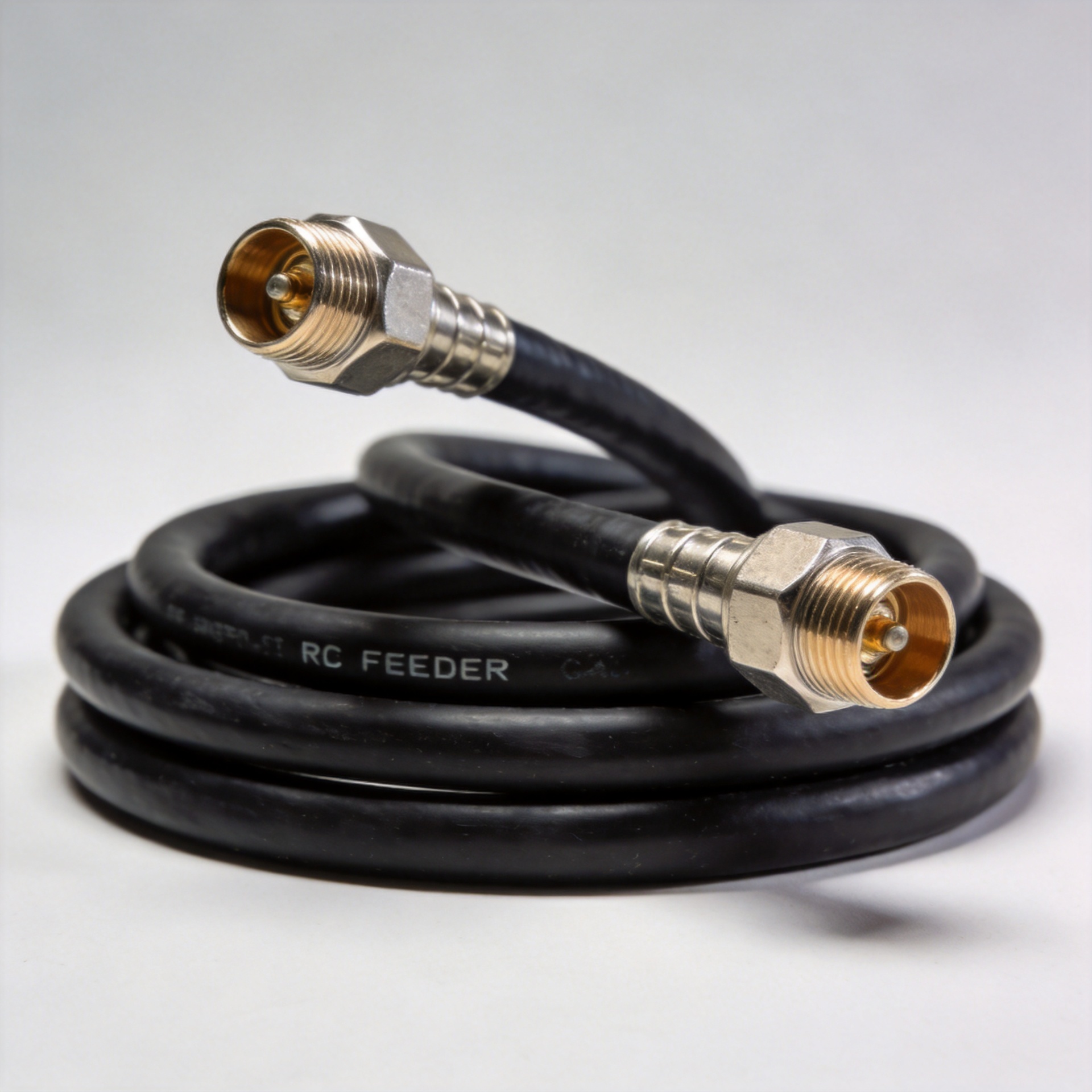
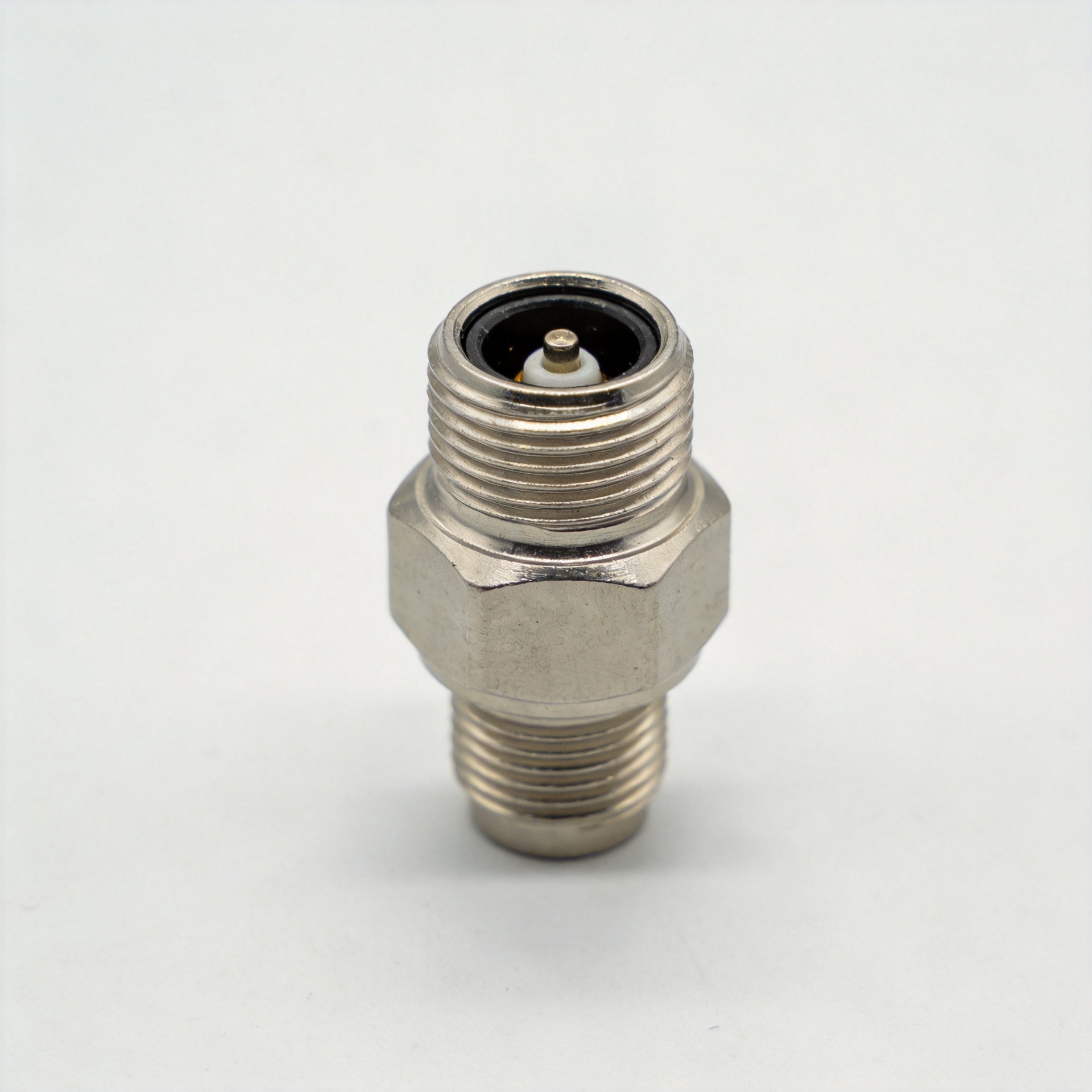
EN
EN

N-Type RF Connector Selection Guide: Male, Female, and Cable-Specific Models for LMR400 and RG213
Selecting the right n connector for a given application isn't difficult once you understand three decision layers: form factor, cable compatibility, and electrical suitability for your frequency band and deployment environment.
This guide walks through each layer in sequence — the approach an RF systems engineer takes for a procurement specification, not a product brochure.
Step 1: Selecting the Right Form Factor — Male, Female, and Right-Angle N Connectors
The first selection decision has nothing to do with frequency range or impedance. It's about how your connector mates within the system.
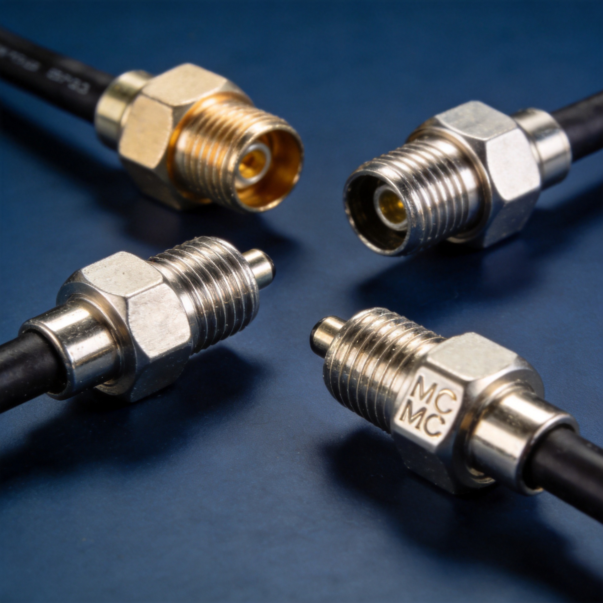
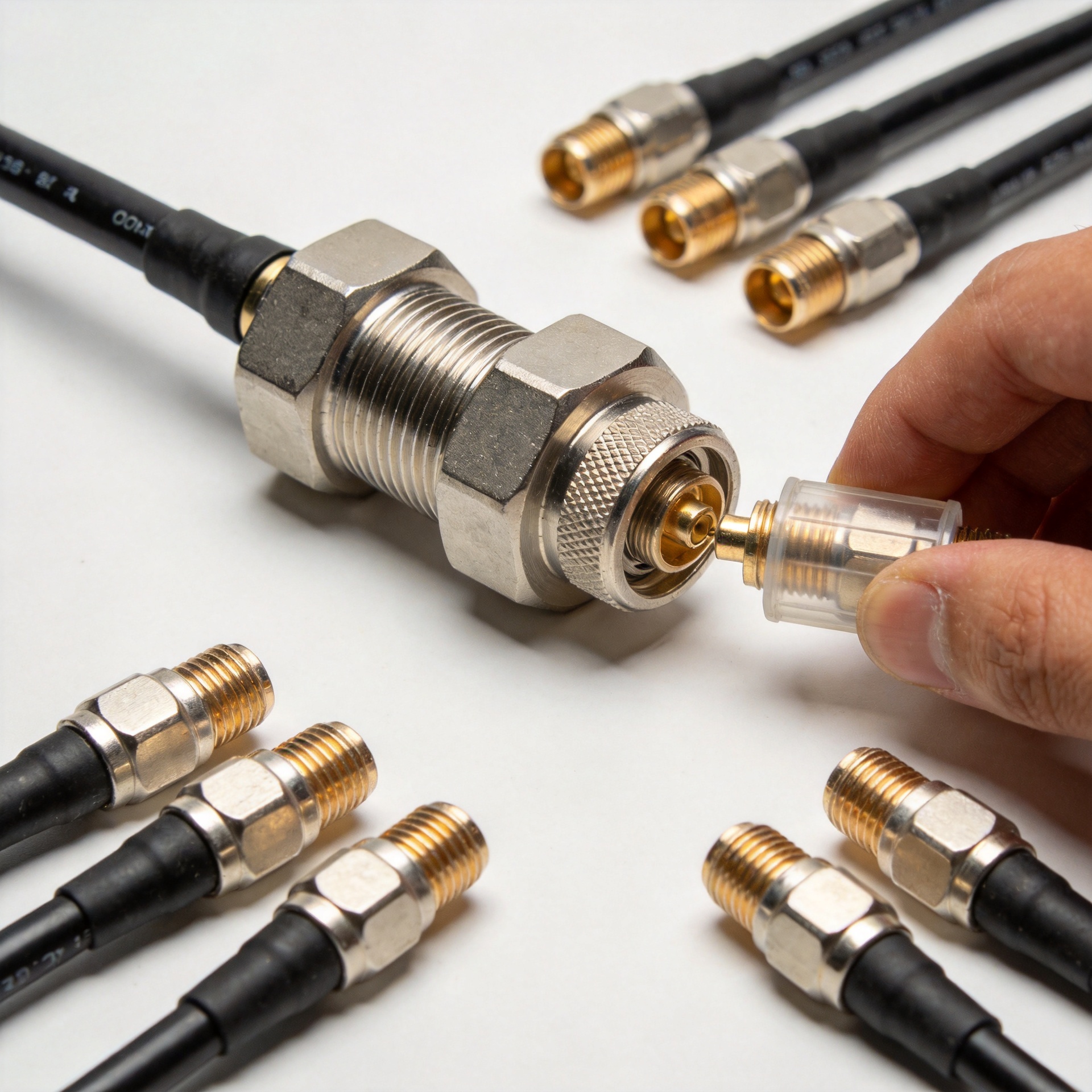
- N male (plug): Used on cable ends that terminate at equipment ports, panel jacks, or bulkhead adapters. The male center pin inserts into the female socket. Most cable assembly terminations use an N male on at least one end.
- N female (jack): Used as the fixed side of a connection — bulkhead receptacles, chassis-mount jacks, and antenna base ports. The n female connector receives the male plug and is typically panel-mounted or equipment-integrated.
- Right-angle: Chosen when cable routing geometry prevents a straight connector from fitting without a sharp bend that would damage the cable or create a mechanical stress point. Right-angle configurations trade some VSWR performance for installation flexibility. At 9–11 GHz, right-angle N connectors are rated at VSWR max 1.5 (−14 dB) compared to 1.30 (−18 dB) for straight configurations per MIL-C-39012. For most telecom band applications below 6 GHz, this difference is negligible. For higher-frequency microwave systems, it deserves evaluation.
The selection logic is straightforward: match the connector gender to your system's mating interface, and choose straight or right-angle based on the physical constraints of your cable route.
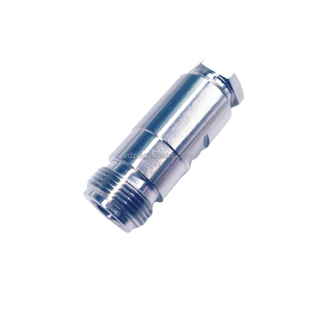
Step 2: Cable Compatibility — Matching N Connectors to LMR400, RG213, LMR200, and LMR195
A common procurement error is selecting a type n connector that is electrically correct but dimensionally mismatched to the cable outer conductor diameter. Crimp, clamp, and solder versions are dimensioned for specific cable ODs, and the wrong crimp ferrule will not produce a reliable assembly regardless of the electrical specification.
| Cable Type | Nominal OD | Compatible N Connector | Notes |
|---|---|---|---|
| LMR-400 / RG-8 / RG-213 / RG-214 | ~10.8 mm (0.405") | N crimp for 0.405" OD | These cables share compatible N connector dimensions; source a single SKU for this cable family |
| LMR-200 | ~5.4 mm (0.195") | N connector for LMR-200 series | Distinct from LMR-400 family; verify crimp ferrule inner diameter before ordering |
| LMR-195 / RG-58 / 3D-FB | ~5.0 mm class | N connector for LMR-195 / RG-58 class | Confirm OD tolerance with manufacturer; shares approximate range with LMR-200 |
| LMR-600 | ~15.8 mm | N connector for 0.590" OD | Significantly larger than LMR-400 series; requires different ferrule — do not substitute |
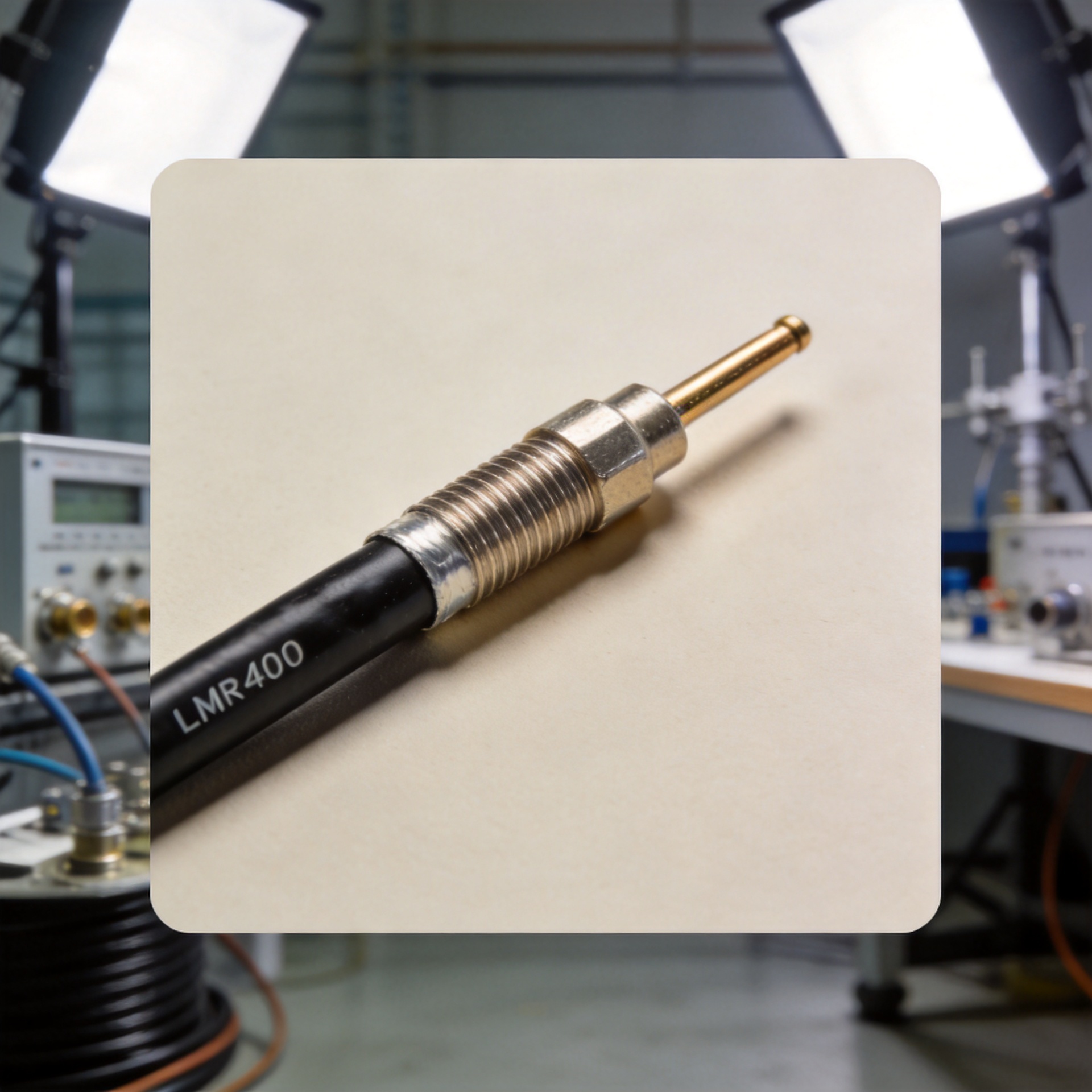
For RG213 and LMR400 applications, two of the most widely used cable types in telecom base station and antenna feeder systems, a n connector designed for the 0.405" OD class fits both. The practical implication: if your deployment uses a mix of RG-8, RG-213, and LMR-400 from different supply sources, you can standardize on a single N connector part number for that cable family.
For LMR-195 or LMR-200 applications, the connector geometry is different. If sourcing for a deployment with mixed cable types, specify separate connector SKUs for each cable diameter class.
For LMR-400, RG-213, and RG-8 cable terminations, our Factory High Quality N Male Connector for RG213 RG8 LMR400 Cable is designed for this specific cable family. For LMR-195, LMR-200, RG-58, and 3D-FB applications, our RF N Female Connector for RG58 / 3D-FB / LMR195 / LMR200 Cable covers the smaller-diameter cable range.
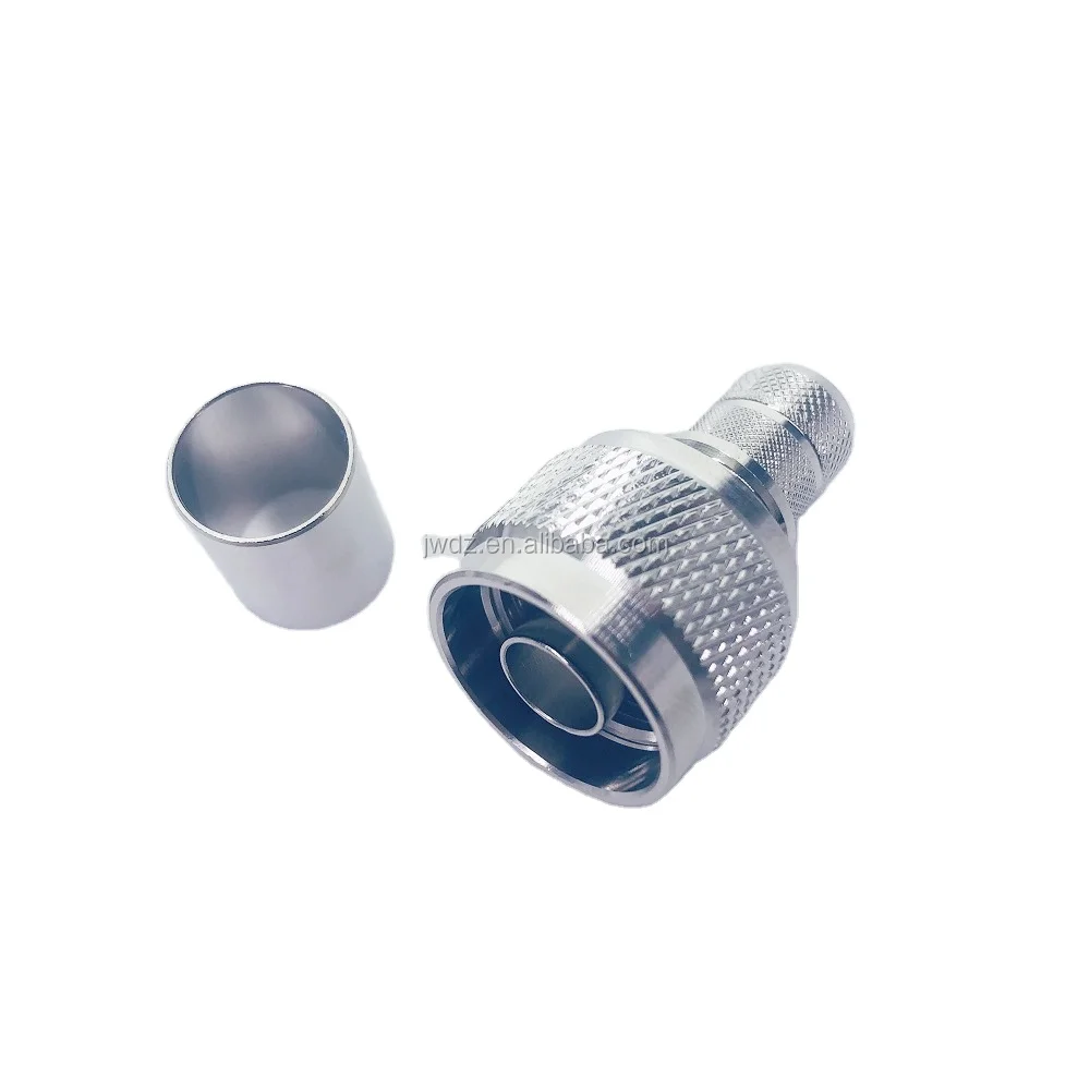
Step 3: Electrical Specification Review — 50 Ω, DC–11 GHz, VSWR, PIM, and Power Handling
Standard N-type connectors operate from DC to 11 GHz at 50 Ω nominal impedance. This covers the majority of cellular infrastructure, base station antenna, and broadcast feeder applications. Extended-range designs rated DC–18 GHz exist for microwave backhaul and precision test applications, at higher cost and tighter manufacturing tolerances.
The electrical parameters that matter for a procurement specification:
- Impedance: 50 Ω nominal (consistent across all standard N-type designs)
- Frequency range: DC–11 GHz standard; confirm if extended-range capability is required for your application
- VSWR: Straight MIL-C-39012 connectors rated at 1.30 max (−18 dB) from DC–11 GHz; right-angle versions at 1.5 max (−14 dB) from 9–11 GHz
- PIM (Passive Intermodulation): For base station and DAS applications, specify PIM performance at −166 dBc minimum with 2 × 43 dBm test inputs. PIM failures in the field most commonly trace back to contact geometry variation in low-quality plating batches rather than connector design
- Power handling: Typically 300 W continuous at 10 GHz / 25°C; apply thermal derating for high-ambient-temperature outdoor installations
- Contact resistance: Center contact max 1 mΩ, outer contact max 4 mΩ; contact resistance variation across a procurement batch is a useful incoming quality indicator
- Operating temperature: −65°C to +165°C for standard constructions with PTFE insulators and brass bodies
One parameter worth highlighting for B2B buyers: voltage rating is 500 VRMS continuous, with dielectric withstanding voltage rated to 1500 VRMS. For most antenna feeder applications this is not a limiting factor, but it matters for certain RF power distribution and load testing configurations.
Step 4: Outdoor and High-Reliability Procurement Checklist — IP Rating, Weatherproofing, and Batch Verification
For outdoor antenna installations, IP rating verification is a starting requirement, not a final answer. IP67 when mated (the standard for select N connector models) means tested for temporary water immersion to 1 meter for 30 minutes under IEC 60529. It does not mean ready for all outdoor conditions without installation discipline. An unmated connector left open during a rain event, or a sealing ring that's been improperly seated, will not perform to the rated IP level.
A practical procurement checklist for outdoor RF N connector batches:
- Confirm IP67 mated rating with test standard reference (IEC 60529); verify sealing ring is included and specified for the operating temperature range
- Request PIM specification at stated test conditions; a PIM number without test input power levels and test method is not a usable specification
- Verify crimp ferrule OD matches your cable OD (critical when sourcing for mixed LMR-400 and LMR-200 cable types in the same project)
- Check sealing surfaces and contact plating on sample delivery; visible oxidation or contact surface variation indicates storage, handling, or quality control issues
- For cable assembly batches where PIM performance is a system requirement, request RF sweep test documentation at the assembly level
Batch variation in contact plating is a more frequent failure source than connector design. A n connector that meets spec on paper but ships with contact resistance variation across a batch will cause commissioning problems that are difficult to isolate. Factory direct sourcing with production record traceability addresses this directly.
Applying the Selection Framework
Working through the four steps above converts a connector selection task from a catalog search into a specification-driven procurement decision. The correct n connector for your application is determined by four factors in sequence: cable OD compatibility, installation form factor, electrical requirements for your frequency band, and environmental and reliability requirements for your deployment setting.
For the majority of telecom infrastructure applications using LMR-400, RG-213, or RG-8 feeder cable, the selection path leads to N male crimp connectors for the 0.405" OD cable family. For smaller-diameter LMR-195 and LMR-200 systems (common in indoor DAS, lower-power antenna runs, and laboratory assemblies), the geometry changes and the required connector part number changes with it.
If you are sourcing N connectors for a specific infrastructure project, or evaluating cable assembly options for bulk procurement, contact Zhenjiang Jiewei directly. With 25 years of focused manufacturing experience in RF connectors and cable assemblies for telecom and broadcast applications, we can match connector specifications to your exact cable type and termination requirements, with factory direct traceability that makes batch consistency verifiable rather than assumed.