EN

N-Type vs. 4.3-10 RF Attenuators: Interface Selection Guide
A type n attenuator is often the straightforward choice when an RF path already uses N connectors. But when a project is being redesigned for dense radio equipment, the interface decision deserves more than a “match what is on hand” approach. N-type and 4.3-10 attenuators can both serve 50-ohm RF systems, yet they solve different mechanical and installation problems. The right choice comes from validating the complete signal path: mating interfaces, operating band, attenuation value, power duty, access for installation, and the conditions around the enclosure.
For telecom equipment makers, lab teams, integrators, and OEM buyers, this guide separates interface selection from electrical qualification. That distinction prevents a common purchasing mistake: choosing a connector style first, then discovering that the selected attenuation or power rating does not fit the actual RF budget.
Start with the System Boundary, Not the Attenuator Body
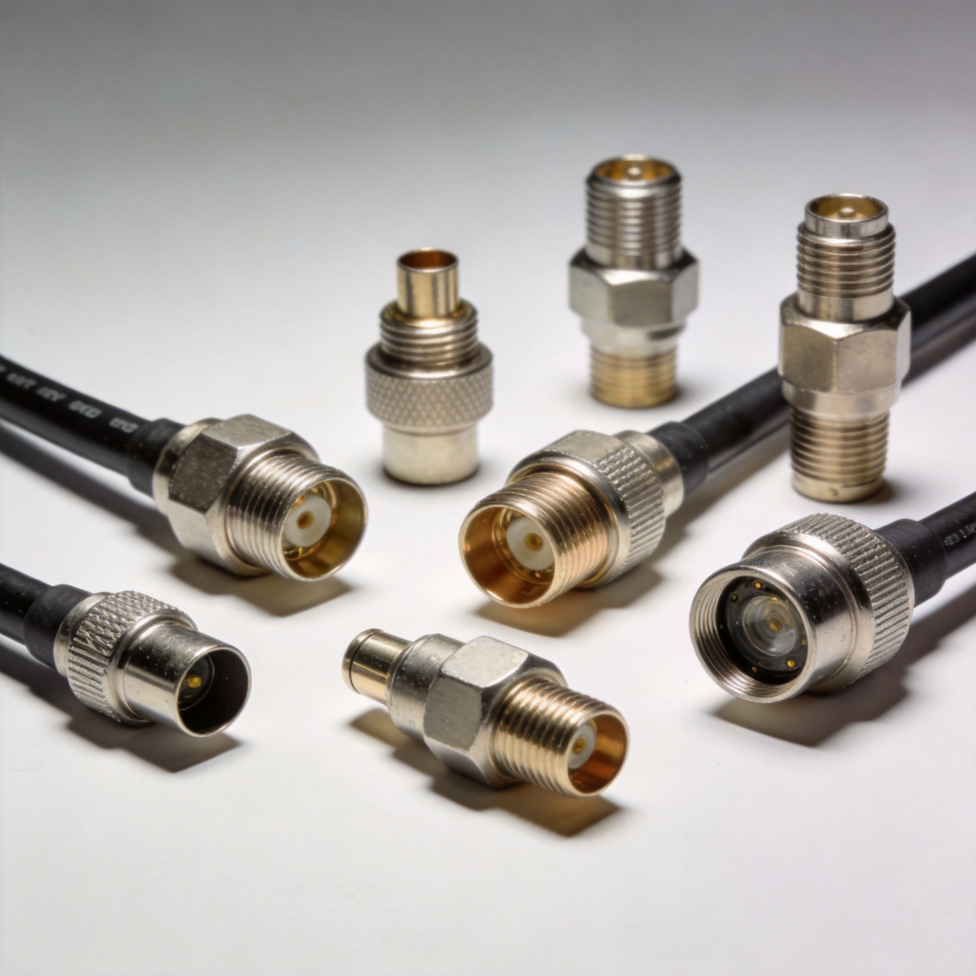
The first question is simple: what interfaces exist immediately upstream and downstream? A type n attenuator is normally the lowest-risk choice in an established N-interface run because it can be inserted without adding adaptors. Fewer transitions mean fewer mating surfaces to inspect and fewer opportunities to introduce an unexpected mechanical mismatch.
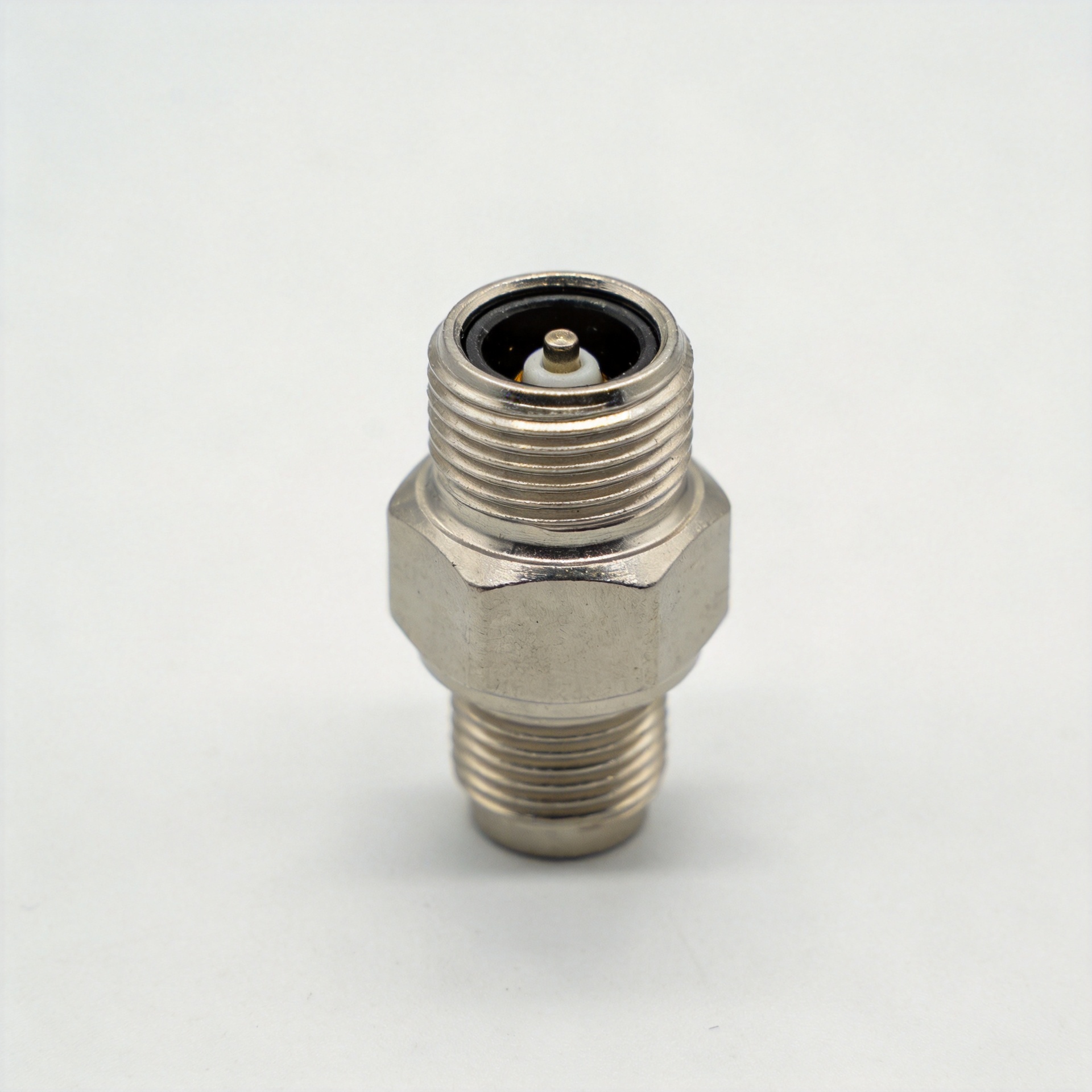
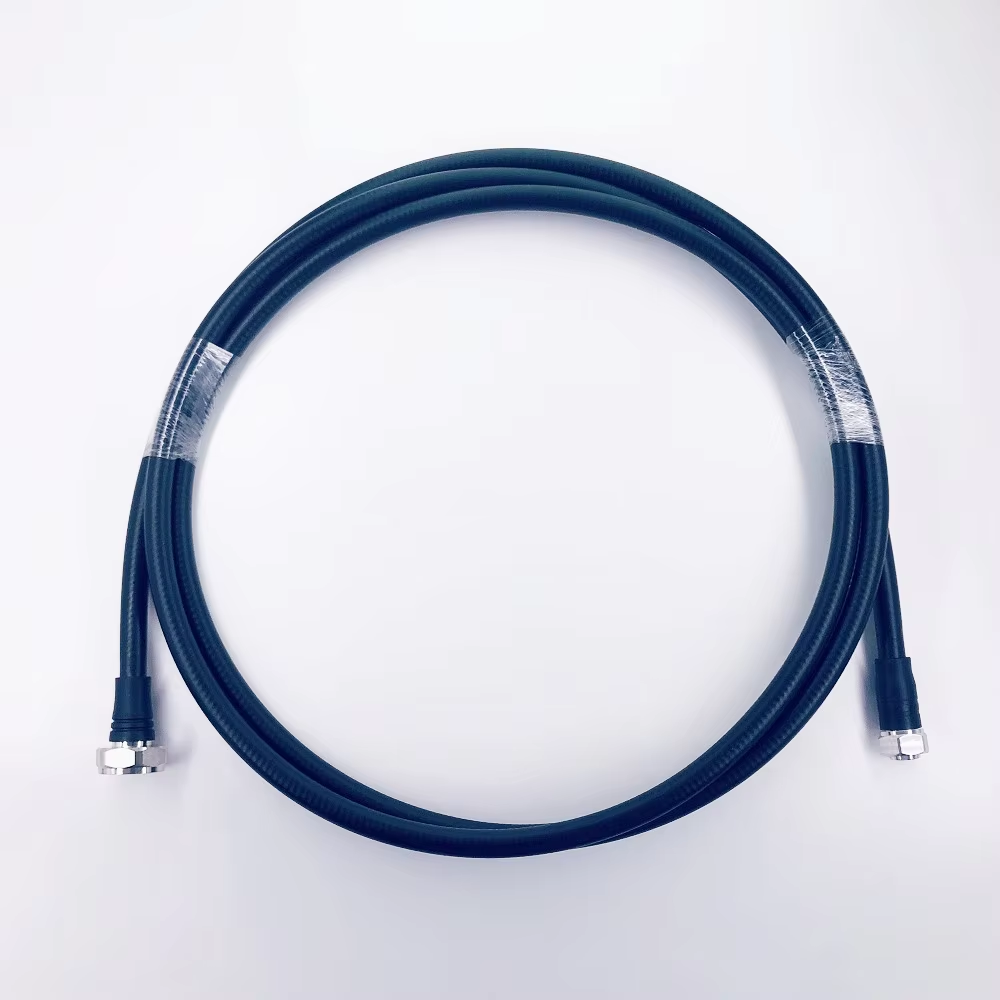
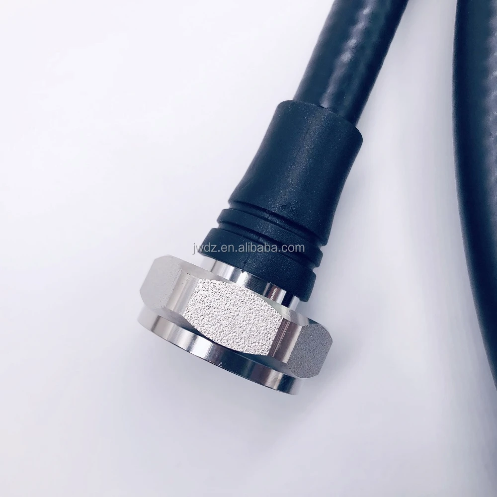
4.3-10 is more commonly evaluated when the surrounding equipment already uses that interface or when the design team is standardizing a compact, high-density radio architecture. It is not automatically a performance upgrade for every legacy path. If a 4.3-10 attenuator needs N-to-4.3-10 adaptors at both ends, the assembly becomes longer and adds interfaces that must be specified, torqued, and maintained.
- Choose N-type first when existing ports, jumpers, test equipment, and spares are N-based.
- Choose 4.3-10 first when the radio-side interface is already 4.3-10 and space or installation density is a priority.
- Do not mix interfaces by default; use an adaptor only when a controlled transition is genuinely required.
N-Type vs. 4.3-10: What the Interface Changes
| Selection factor | N-type attenuator | 4.3-10 attenuator |
|---|---|---|
| Best fit | Existing N-interface networks, test setups, and field replacements | Systems already built around 4.3-10 ports and dense equipment layouts |
| Integration priority | Direct compatibility with a mature installed base | Compact interface strategy and installation flexibility |
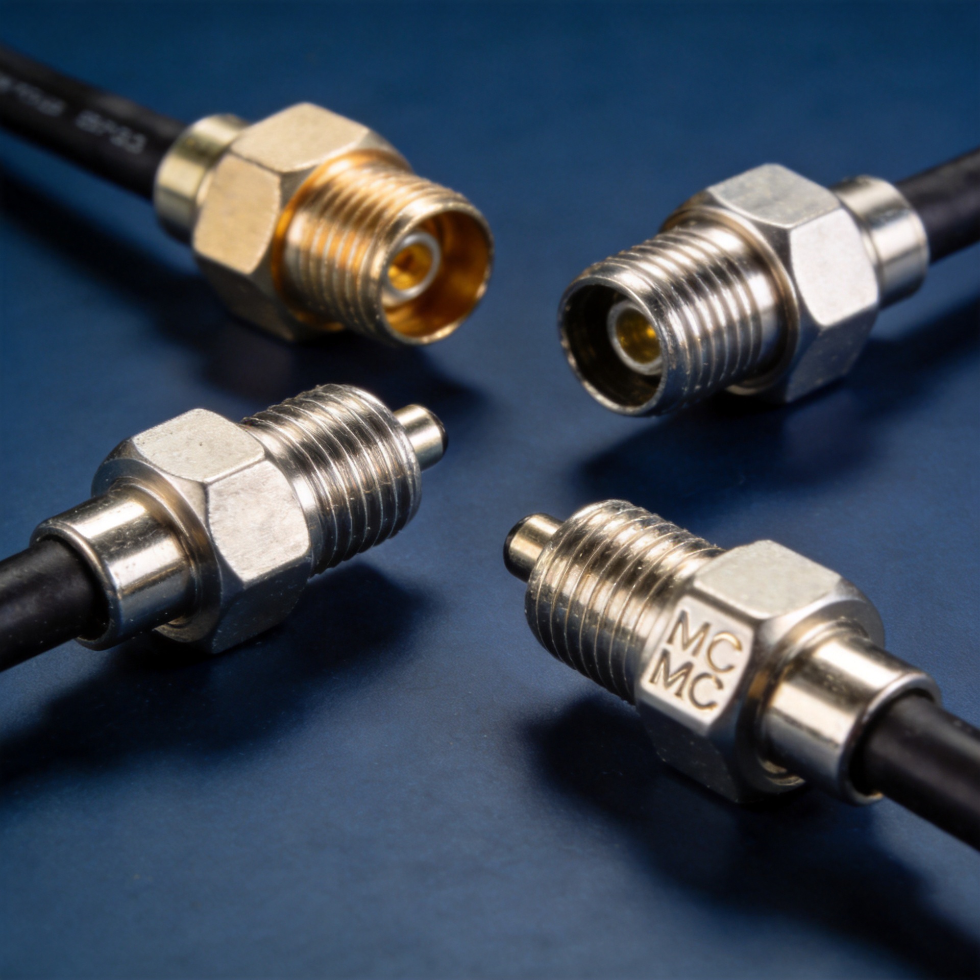
| Procurement check | Confirm N male/female orientation on both ends | Confirm the exact 4.3-10 coupling style and mating-part compatibility |
| Common mistake | Assuming all N-interface parts share the same electrical limits | Using it as an adaptor substitute without reviewing the whole assembly |
Connector family is only one layer of the decision. A type n attenuator must still be selected for the correct impedance, fixed attenuation value, frequency range, average and peak power exposure, and environmental requirements. The same principle applies to a 4.3-10 part.
Compare Electrical Requirements Before Selecting Either Interface
1. Confirm the system impedance
Most RF attenuator applications in communication and test systems are designed around 50 ohms, but that must be confirmed from the system documentation. The attenuator, cable assemblies, connectors, and instrument ports should be evaluated as one controlled-impedance path. An interface that mates mechanically is not enough if the electrical specification is wrong for the system.
2. Define attenuation as an RF-budget requirement
Start with the required signal reduction in dB, then confirm the tolerance and flatness needed across the operating band. Avoid selecting a type n attenuator simply because a common 10 dB or 20 dB value is available. In a receiver-protection, calibration, or level-setting application, the desired loss must be tied to the actual input level and permissible operating range of the downstream device.
3. Validate frequency over the entire operating band
“Up to” frequency claims are not a substitute for a part-specific datasheet review. Check the specified band, return-loss or VSWR behavior, and attenuation performance at the frequencies that matter to the installation. A broadband system should be checked at the band edges, not only at a center frequency.
4. Treat power as a duty-cycle question
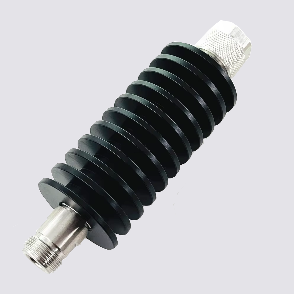
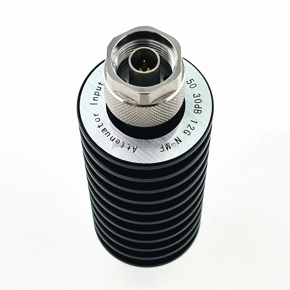
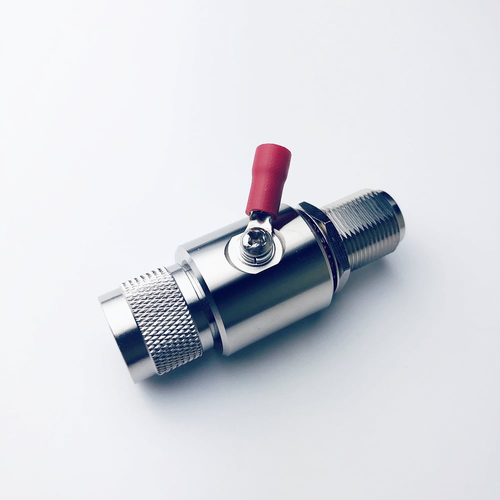
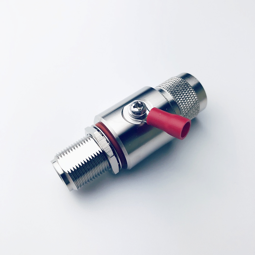
Average power, peak power, waveform, ambient temperature, airflow, and mounting all influence the thermal load on a fixed attenuator. For example, the matched catalog item is described as a 200 W N coaxial attenuator with listed options reaching bands up to 18 GHz and fixed values such as 20, 30, 40, and 60 dB. That makes it a useful starting point for an N-based path, but buyers should confirm the exact selected configuration and its datasheet limits before release.
Installation Environment Can Tip the Decision
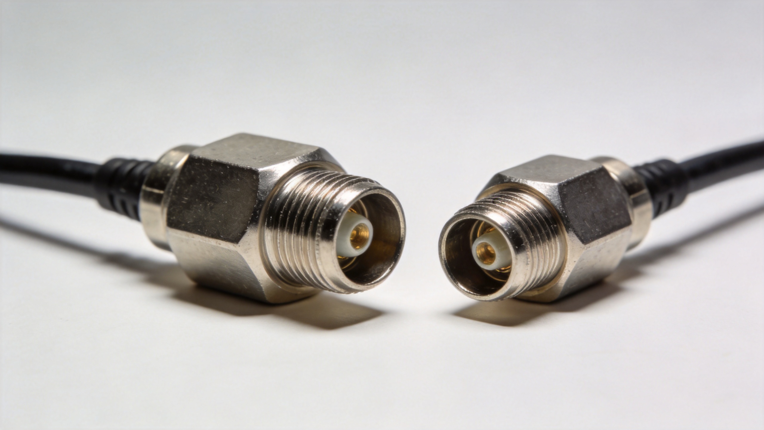
In a roomy bench setup, the established connector family may matter more than package compactness. In a crowded base-station cabinet or radio enclosure, cable routing, hand clearance, bend radius, and service access become decisive. A 4.3-10 architecture can be attractive where compact installations are already planned around that interface. Conversely, forcing an N-to-4.3-10 conversion into a legacy run may complicate a maintenance task that was otherwise simple.
For either interface, establish a written installation check: connector gender, mating torque procedure, cable strain relief, clearance around the attenuator body, labeling, and inspection after rework. These steps are especially important where repeated test connections or field servicing can loosen the mechanical discipline of the RF path.
A Practical Procurement Checklist
- Map every port and jumper in the proposed signal path, including connector family and gender.
- Confirm 50-ohm compatibility and the required fixed attenuation value with the RF budget owner.
- Check the full frequency band, not just the nominal operating frequency.
- Calculate expected average and peak power at the attenuator location; review thermal conditions.
- Choose N-type when it eliminates unnecessary adaptors in an N-based system.
- Choose 4.3-10 when the surrounding equipment already uses it and compact installation is a documented requirement.
- Request the exact part datasheet and verify mechanical orientation before purchase approval.
Type N Attenuator Specification Worksheet
Use this short worksheet to qualify each type n attenuator request before a purchase order is released. Record the required attenuation, frequency band, power duty, and both connector genders for the type n attenuator. Confirm that the proposed type n attenuator has 50-ohm impedance and that its datasheet covers the actual operating band. For a replacement, compare the installed type n attenuator length and mounting clearance with the new type n attenuator.
- Does the type n attenuator mate directly with both adjacent interfaces?
- Is the type n attenuator attenuation value correct at the required band edges?
- Is the type n attenuator power rating suitable for the expected average and peak load?
- Does the type n attenuator connector gender eliminate the need for an adaptor?
- Can the type n attenuator be installed and serviced with the available cable clearance?
- Has the type n attenuator part number been checked against the final bill of materials?
When a 4.3-10 system is under review, apply the same worksheet to the 4.3-10 option and compare the complete assemblies rather than comparing connector names in isolation. A type n attenuator remains the sensible selection when it preserves a direct, qualified N-interface signal path. This worksheet also helps procurement teams prevent an otherwise compatible type n attenuator from being approved with the wrong dB value, band, or power class.
When an N-Type Attenuator Is the Better Fit
A type n attenuator is usually the practical option for upgrades, repairs, test fixtures, and assemblies that already rely on N ports. It preserves interface consistency, simplifies spare-parts planning, and avoids unnecessary transitions. For a direct example of an N-interface option, review the 200W N coaxial attenuator with listed fixed-dB options only after confirming its exact frequency, power, attenuation, and connector-gender configuration against your application.
When the project is new and the equipment ports are not yet fixed, compare the two interfaces as part of the full system architecture. The better choice is the one that meets electrical requirements while reducing transitions, space conflicts, installation ambiguity, and lifecycle service burden.
Conclusion: Select the Interface That Simplifies the Qualified RF Path
The N-type versus 4.3-10 decision is not a contest between connector names. Select a type n attenuator where it delivers direct, controlled compatibility in an N-based RF path. Select 4.3-10 when the system is already designed for it and its compact installation advantages support the project. In both cases, finalize the order only after the interface, impedance, frequency band, attenuation value, power duty, and installation conditions have been verified together.