EN

SMA to SMA Cable Assembly Guide: Frequency and Connector Choices
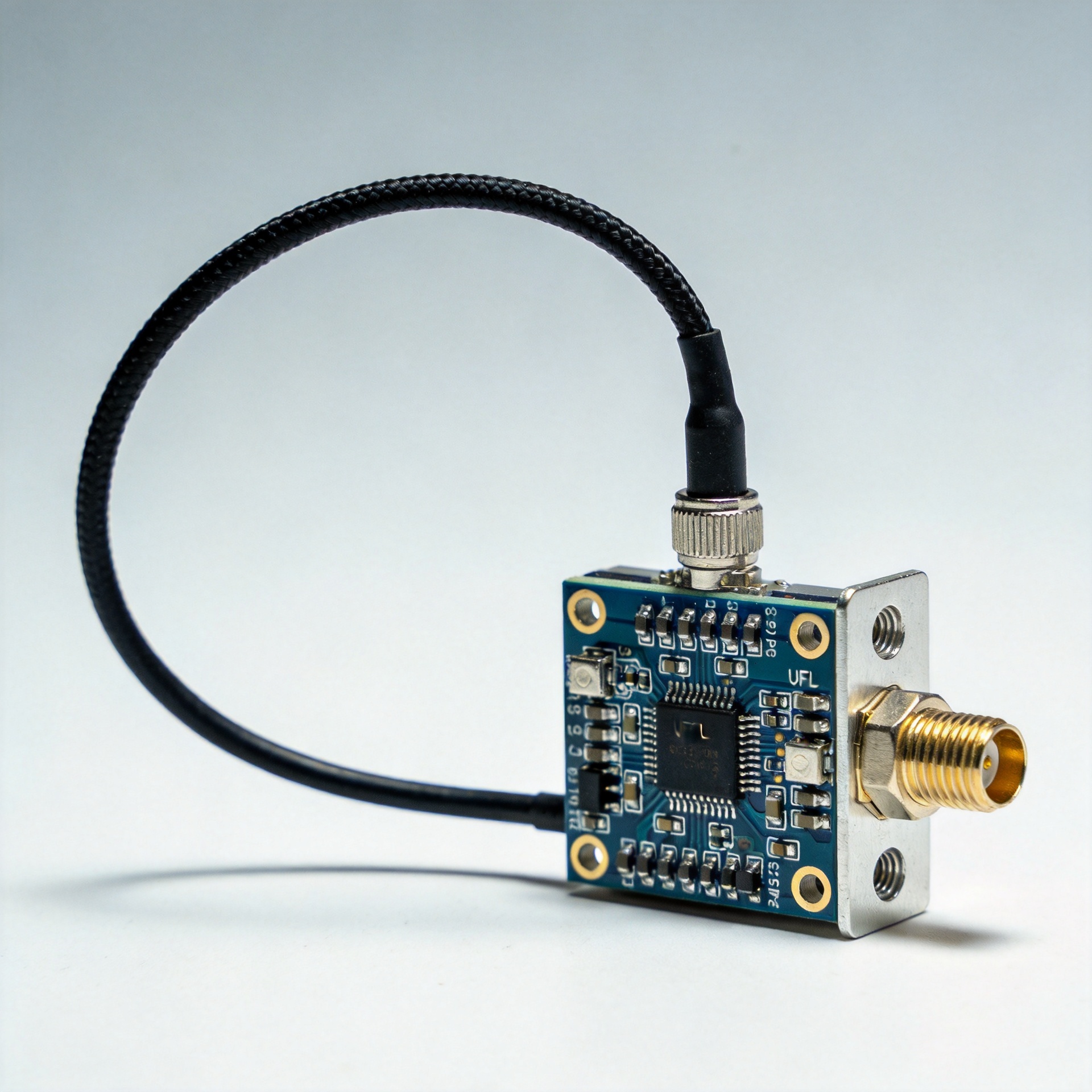
Choosing an SMA to SMA cable assembly looks straightforward: the same compact threaded interface appears at both ends. In a real RF design or purchase order, however, that label leaves important decisions unresolved. Frequency range, cable construction, length, bend radius, connector gender, polarity, and termination geometry all affect whether the delivered assembly fits the signal path and the installation.
For procurement teams and RF engineers, the most reliable approach is to start with the required operating band and then work outward to the cable and mechanical configuration. This prevents a common mistake: approving a familiar SMA interface before confirming that the complete assembly—not merely the connector family—supports the electrical and physical conditions of the application.
Start with the required frequency, not the connector name
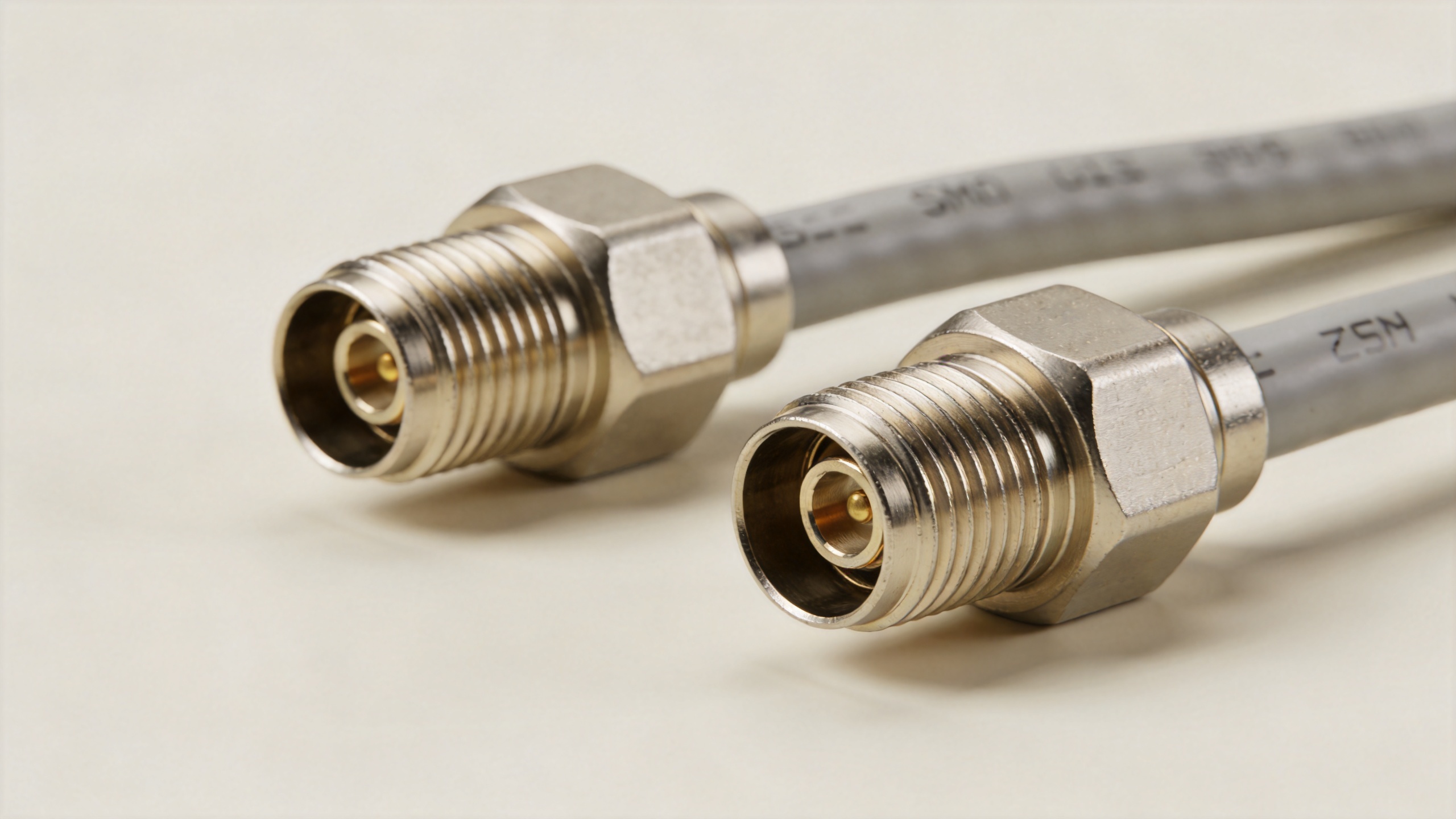
An SMA interface is a 50-ohm threaded RF connector family widely used in test equipment, compact radio modules, antennas, and microwave assemblies. Many standard SMA references describe operation to 18 GHz, while specific designs can be rated differently and higher-frequency variants are available. That distinction matters. A connector marked “SMA” does not by itself define the usable frequency of an SMA to SMA cable assembly.
Set the requirement from the highest frequency that will actually pass through the link, then request the assembly’s rated frequency range, insertion-loss data, and return-loss or VSWR data at relevant frequencies. Include margin for the operating band and verify the test conditions. Cable diameter, dielectric construction, connector design, and termination quality can all limit real-world performance.
A higher frequency rating is not automatically the better choice. A higher-rated assembly may be less flexible, more expensive, or unnecessary for a low-frequency link. Match the performance tier to the system requirement rather than over-specifying every short jumper.
Confirm the SMA interface at both ends
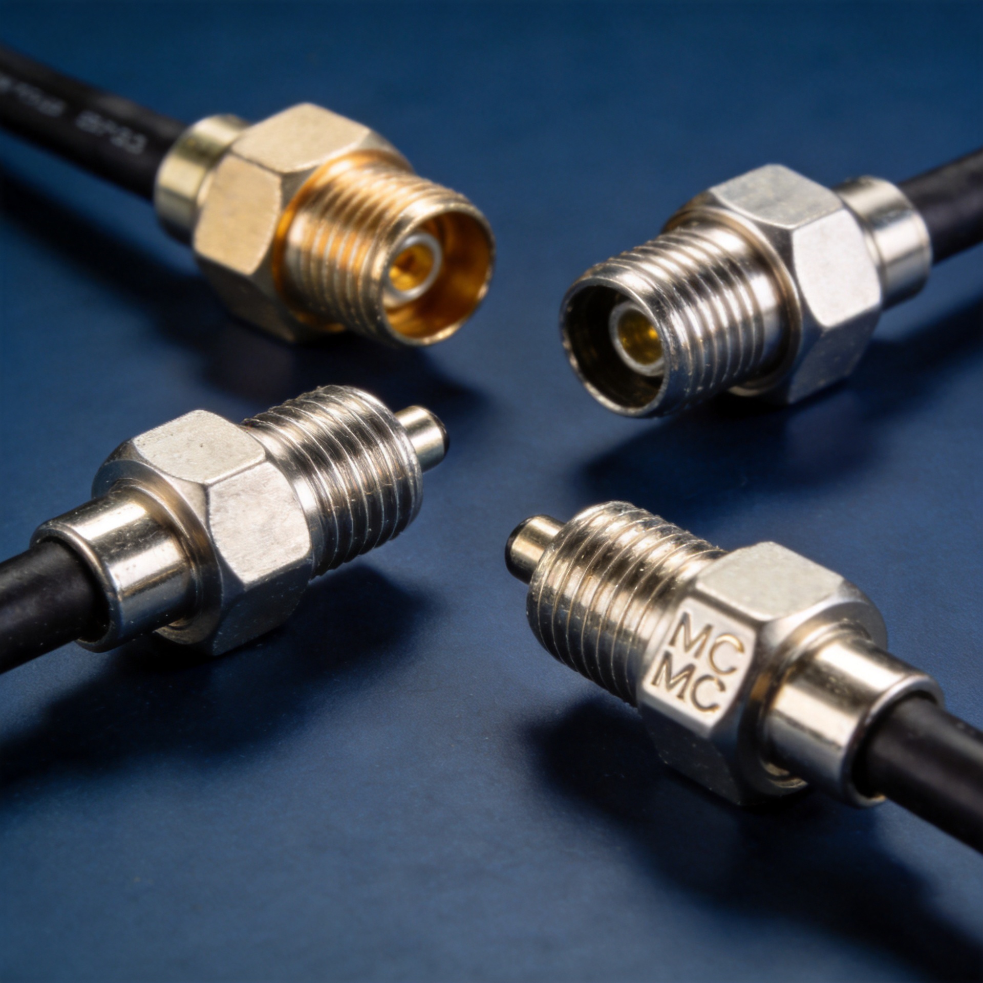
“SMA to SMA” must be translated into an exact end-to-end configuration. Specify whether each end is a plug or jack, straight or right-angle, bulkhead or cable-mounted, and standard SMA or reverse-polarity SMA. Standard SMA and RP-SMA are not interchangeable simply because their outer shape is similar.
For a custom RF cable assembly, add the mating-interface details from the equipment drawing to the RFQ. Confirm gender by the center contact as well as the coupling geometry. This is especially useful when the assembly connects a panel port to a radio, filter, test fixture, or antenna feed, where a wrong gender can trigger an adapter workaround. An added adapter means another interface in the signal path and another point to manage in the return-loss budget.
| Selection item | What to verify | Why it matters |
|---|---|---|
| Interface type | Standard SMA or RP-SMA; 50-ohm system impedance | Avoids a mechanical fit with an incompatible electrical or polarity arrangement. |
| Gender | Plug or jack at each end, including the center contact style | Prevents late-stage adapters and extra RF discontinuities. |
| Geometry | Straight, right-angle, bulkhead, or panel-mount termination | Determines clearance, routing, and strain at the equipment port. |
| Frequency rating | Assembly-level rating and test frequency points | Confirms that the specified cable and connector combination suits the band. |
Choose the cable construction around loss, flexibility, and routing
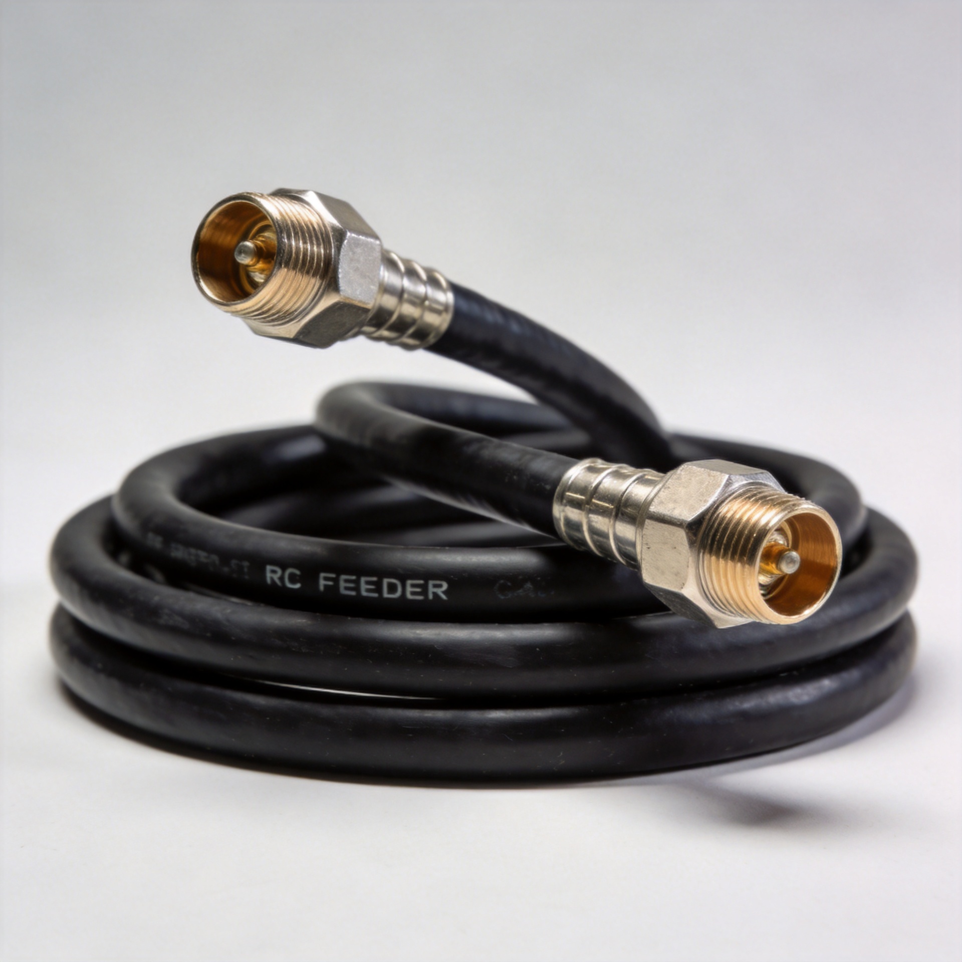
The cable is not a passive detail between two SMA ends. In an SMA to SMA cable assembly, it defines much of the insertion loss, flexibility, shielding, minimum bend radius, and physical durability. A thin flexible cable may simplify routing inside a compact enclosure; a semi-rigid or low-loss construction may be more suitable when microwave performance and shape retention take priority.
Think of the decision as a three-way tradeoff. Longer runs generally need closer attention to attenuation at the highest operating frequency. Tight routes need a cable whose minimum bend radius fits the installation without stressing the dielectric or connector termination. Repeated movement requires a flex-capable construction and strain relief that match the service cycle. Cable routing dictates connector geometry more often than an early BOM review suggests.
Ask the supplier to confirm cable type, nominal length, tolerance, minimum bend radius, jacket material, shielding approach, and any phase-matching requirement. For multi-channel equipment, electrical-length consistency can be just as important as physical length. A well-written RFQ keeps these requirements together rather than listing “SMA cable” as a generic line item.
Use connector orientation to protect the installation
So that is the electrical side of the decision. Now—and this is where many specifications fall short—the mechanical interface. A straight SMA plug is compact and direct, but it may force the cable to bend immediately beside a panel or board. A right-angle configuration can reduce clearance pressure, although its orientation must match the actual route and enclosure geometry.
Before release, review the assembly in the installed position: connector access, wrench clearance, cable exit direction, bend radius, and the load placed on the cable-to-connector junction. In a vibration-prone, mobile, or frequently serviced system, define the strain-relief and cable-support requirements rather than assuming the connector alone will carry the load.
Specify what must be tested and documented
A drawing and a nominal frequency rating are useful, but they do not replace acceptance criteria. For critical links, request appropriate assembly-level evidence for insertion loss, return loss or VSWR, continuity, and visual workmanship. State the frequency points and reference conditions that matter to the design. If torque is controlled in installation or testing, use the connector manufacturer’s documented guidance for that exact material and interface; published recommendations vary, so there is no universal torque value to copy into every project.
This is particularly important for custom assemblies. A sample confirms the design can work. Production verification helps confirm that the delivered batch follows the same cable, connector, termination, and test assumptions. Buyers who need a repeatable process can also ask for labeling, lot identification, and a clear record of any approved substitutions.
A practical SMA to SMA cable assembly checklist
- Define the system impedance and highest operating frequency.
- Identify standard SMA or RP-SMA, plus plug/jack gender at each end.
- Choose straight, right-angle, bulkhead, or panel geometry from the actual installation layout.
- Select cable construction based on frequency loss, flexibility, shield needs, and bend radius.
- Set finished length, tolerance, jacket, labeling, and phase-match requirements where applicable.
- Request assembly-level electrical test criteria and the relevant test frequencies.
- Review mating, torque, cleaning, and handling instructions before installation.
When a custom assembly is the safer choice
Catalog jumpers are efficient when the length, connector orientation, and cable type already fit the design. A custom SMA to SMA cable assembly becomes more useful when the route is constrained, the link budget is tight, the assembly must repeat across multiple channels, or the equipment has a non-standard panel arrangement. The goal is not customization for its own sake; it is to remove avoidable adapters, excess cable, and installation stress from the RF path.
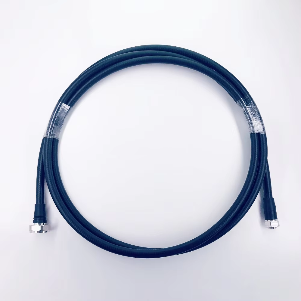
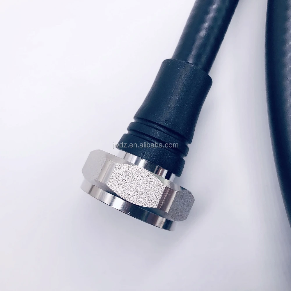
For projects that need an adjacent high-frequency reference, review the 30GHz Low PIM 3506 Cable Assembly With 3.5M To 3.5M product page alongside the actual system requirements. Its availability is a useful reminder to compare the specified interface, cable construction, and stated frequency performance rather than assuming one assembly configuration suits every application.
Conclusion
The right SMA to SMA cable assembly is selected from the inside out: required frequency first, then confirmed connector configuration, then cable construction and installation geometry. A complete specification makes purchasing easier and reduces the risk that a mechanically plausible cable introduces avoidable RF or routing problems. When the application is custom, provide the operating band, both mating interfaces, cable path, length, and acceptance criteria at the start of the conversation.