EN
EN

What Is a BNC Connector? Applications in CCTV, Test Equipment, and RF Systems
When I first started evaluating antenna distribution systems for a multi-site installation, I made an assumption I later regretted: I assumed that any BNC plug would mate with any BNC socket and perform identically. The connectors fit together, so the signal should pass cleanly. It does not. What I had missed was that a BNC plug comes in two impedance versions — 50 Ω and 75 Ω — that are physically interchangeable but electrically mismatched. That mismatch cost us a calibration session and a cable replacement run. If you are selecting a BNC connector for CCTV, RF instrumentation, or broadcast work, understanding the difference before you spec a part is worth the ten minutes it takes.
What Is a BNC Connector?
BNC stands for Bayonet Neill-Concelman, named after its inventors Paul Neill and Carl Concelman. Originally developed in 1944 for military radio equipment, the BNC connector became the de facto quick-connect interface for coaxial cable across video, RF, and test-and-measurement systems. It is a miniature RF connector designed for signals ranging from DC up to approximately 4 GHz on standard-grade designs, with precision variants extending to 12 GHz for broadcast and high-speed digital video.
The bayonet mechanism works by inserting the BNC male connector into a port and rotating it roughly one-quarter turn until two locking pins seat into the bayonet slots. The connection locks without tools and releases equally fast — a useful property in environments where connect-disconnect cycles are frequent, such as oscilloscope probe switching in a test lab or feed routing in a broadcast facility.
50 Ω vs 75 Ω BNC: The Impedance Choice That Determines Signal Quality
The misconception that trips up engineers new to RF interconnects is that physical compatibility implies electrical compatibility. A 50 Ω and a 75 Ω BNC plug mate with equal ease. The problem is invisible on a casual inspection — it shows up in signal reflections and insertion loss. Mixing impedances creates a mismatch at the interface that degrades return loss and, in video systems, introduces ghosting and noise artifacts that are difficult to trace back to a connector.
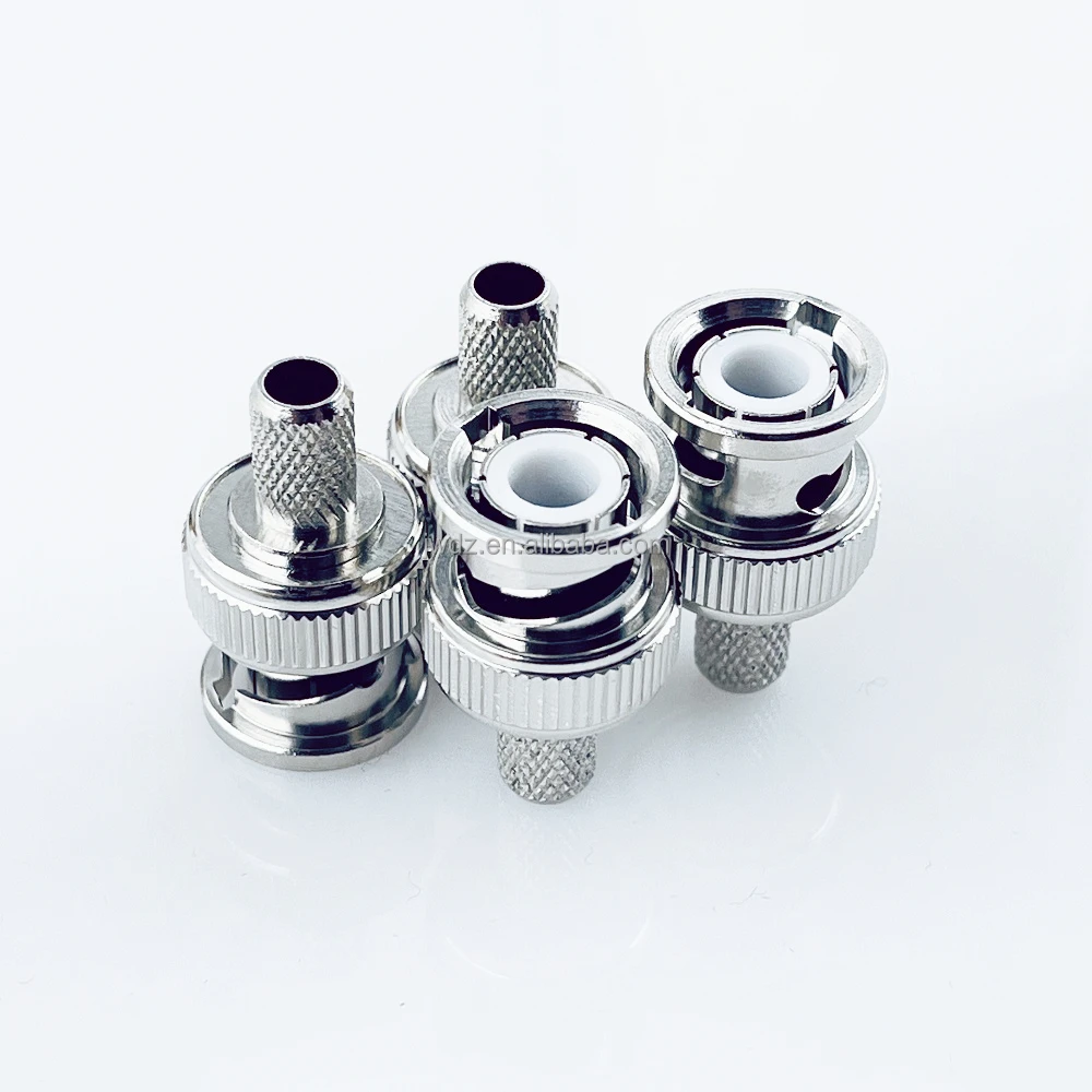
How do you identify which type you are holding without a VNA? The most reliable field method involves the center-pin interface. On a 50 Ω BNC plug, you will see a white dielectric material surrounding the center pin at the mating face. On a 75 Ω BNC plug, that dielectric is absent — the center pin is surrounded by an air gap. This physical difference exists because the two impedance values require different dielectric geometries to maintain their characteristic impedance at the connector interface.
- 50 Ω BNC: RF instrumentation, oscilloscopes, signal generators, wireless communication test systems. The 50 Ω standard maximizes power transfer in RF applications and supports VSWR of 1.3:1 or better at DC to 4 GHz.
- 75 Ω BNC: CCTV surveillance camera cabling, HD-SDI and 12G-SDI broadcast video, DS3 telecom. The 75 Ω standard minimizes loss for video signals, which is why a BNC connector for CCTV camera systems is typically a 75 Ω part.
A counterintuitive point worth flagging: higher frequency capability does not make a connector better for your application. A precision BNC rated to 12 GHz on a 75 Ω CCTV run is no more useful than a standard part — and costs more. Match the spec to the actual operating frequency and impedance of your cable and equipment, not to a headline performance number.
BNC Connector Applications: CCTV, RF Test Equipment, and Broadcast
The breadth of BNC use comes from its combination of quick mating, moderate size, and solid RF performance at the frequencies most video and RF systems operate in.
CCTV Surveillance Systems
A BNC connector for CCTV camera systems is one of the most common installations in the field. Analog CCTV and HD-CVI/TVI/AHD cameras deliver composite or high-definition video over 75 Ω coaxial cable using BNC interfaces at both the camera and the DVR. The bayonet lock handles the repeated disconnections that come with system upgrades and camera replacements without the connector body loosening over time the way a push-fit F-connector would.
RF Test and Measurement
Walk into any electronics lab with an oscilloscope or spectrum analyzer and you will see 50 Ω BNC ports. The BNC became the universal probe interface because it tolerates the high cycle counts of bench work — the MIL-STD-348 interface specification requires a minimum of 500 mating cycles — and because it supports signals up to 4 GHz adequately for the majority of general-purpose RF test tasks. Signal generators, frequency counters, and time-domain reflectometers all standardized on the 50 Ω BNC jack as their front-panel interface decades ago, and the convention persists.
Broadcast and RF Distribution
Broadcast infrastructure relies on BNC across video routers, signal distribution amplifiers, and production switchers. At 12G-SDI frequencies carrying 4K video, precision 75 Ω BNC connectors are specified to maintain low VSWR — 1.22:1 or better up to 6 GHz — across the signal path. The BNC's compact size also makes it practical for densely populated patch panels where space is limited.
BNC Plug vs BNC Jack: Termination Methods for the Male Connector
The BNC male connector (the protruding center pin and rotating bayonet collar side) is the BNC plug. The fixed panel-mount or chassis-mount receptacle is the BNC jack or socket. When you select a BNC plug for field assembly, the termination method determines how the center conductor and outer braid of the coaxial cable are attached to the connector body.
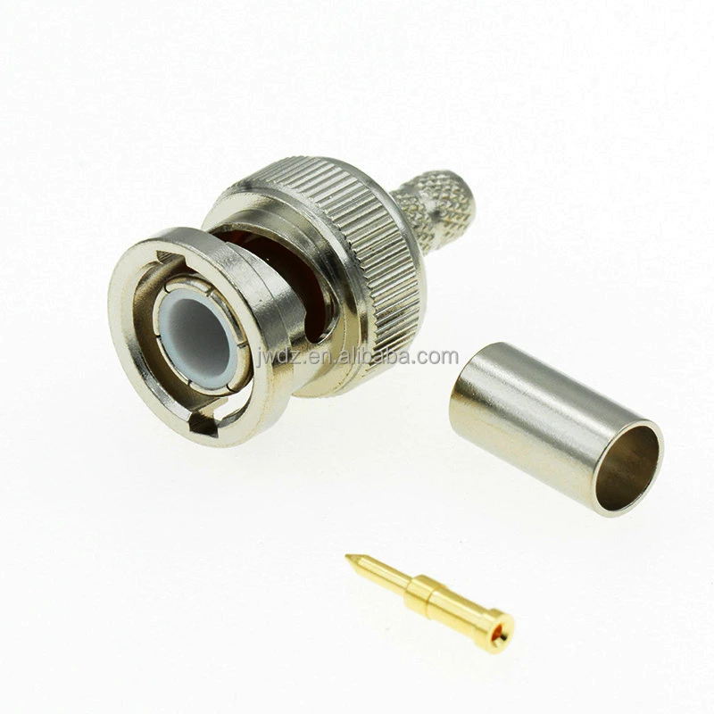
- Solder termination: The center conductor is soldered into the center pin, and the braid is soldered or clamped to the connector body. A straight male solder BNC connector for CCTV camera and TV antenna applications provides a durable, low-resistance bond suited to fixed installations where the cable end will not need frequent re-termination.
- Crimp termination: A dedicated crimp tool collapses the outer ferrule around the cable braid, securing the connector mechanically and electrically in a single operation. A BNC male crimp RF connector for LMR195, 3D-FB, and RG58 cable is a common choice for cable assembly production and field installation work where consistent termination quality and speed matter. The specific crimp ferrule must be matched to the cable's outer diameter.
- Clamp termination: A mechanical clamp grips the cable braid without soldering. Clamp connectors are less common in production but useful when soldering is not practical in the field.
Cable geometry also drives connector selection in ways that spec sheets may not fully capture. When a cable must exit a connector body at a right angle to clear a panel or reach a connector buried behind other cabling, a right-angle BNC plug becomes necessary. The electrical performance of right-angle designs is nominally similar to straight versions at lower frequencies, but insertion loss increases at higher frequencies, so straight connectors are preferred for precision RF paths when physical routing allows.
When to Choose BNC Over SMA, TNC, or N-Type
If your priority is fast field disconnection and your operating frequency is below 4 GHz, BNC is well-suited. If your system runs at 18 GHz or above, SMA or 3.5 mm connectors offer better frequency performance. If you need threaded coupling security in high-vibration environments where the quarter-turn bayonet action could disengage, TNC (the threaded BNC equivalent) provides the same impedance behavior with a more secure mechanical interface. For higher-power applications or connectors exposed directly to outdoor weather without additional housing, N-type provides more more effective weatherproofing and higher power handling at comparable frequencies.
For most CCTV, general broadcast, and test-lab applications below 4 GHz, the BNC connector's combination of quick-connect convenience, standardized interface geometry, and availability across cable types makes it the practical default. Zhenjiang Jiewei Electronic Technology Co., Ltd has manufactured RF connectors, feeder cables, and cable assemblies for over 25 years, supplying telecom infrastructure and broadcast system integrators across Asia, Europe, and North America. Whether you are sourcing solder BNC plugs for a CCTV deployment or crimp BNC male connectors for an RF cable assembly program, matching impedance to your system and termination method to your installation workflow remains the first decision to get right.