EN
EN

What Is a Leaky Feeder Communication System? Underground Wireless Coverage Explained
The global leaky coaxial cable market was valued at $1.42 billion in 2025 and is projected to reach $2.68 billion by 2034, growing at a CAGR of 7.3%. That figure points to a practical reality: as mines go deeper and tunnels grow longer, reliable two-way communication below ground stops being a convenience and becomes a legal and safety requirement. The technology that makes it possible is the leaky feeder communication system, and this article explains what it is, how it works, and why its cable specifications matter.
The Underground Coverage Problem
Conventional radio communication depends on signals bouncing between antennas with line-of-sight or near-line-of-sight paths. Underground, that model fails entirely. Rock walls, concrete linings, sharp tunnel bends, and metallic equipment absorb and scatter radio waves within a few meters of a standard antenna. A team 500 meters into a mine heading may be completely unreachable from the surface, even with high-powered transceivers.
Boosting transmitter power does not fix this. Increasing output creates noise, interference, and — in environments with flammable gases — ignition risk. What underground operations need is a coverage architecture built for the environment, not patched onto it.
How a Leaky Feeder Communication System Works
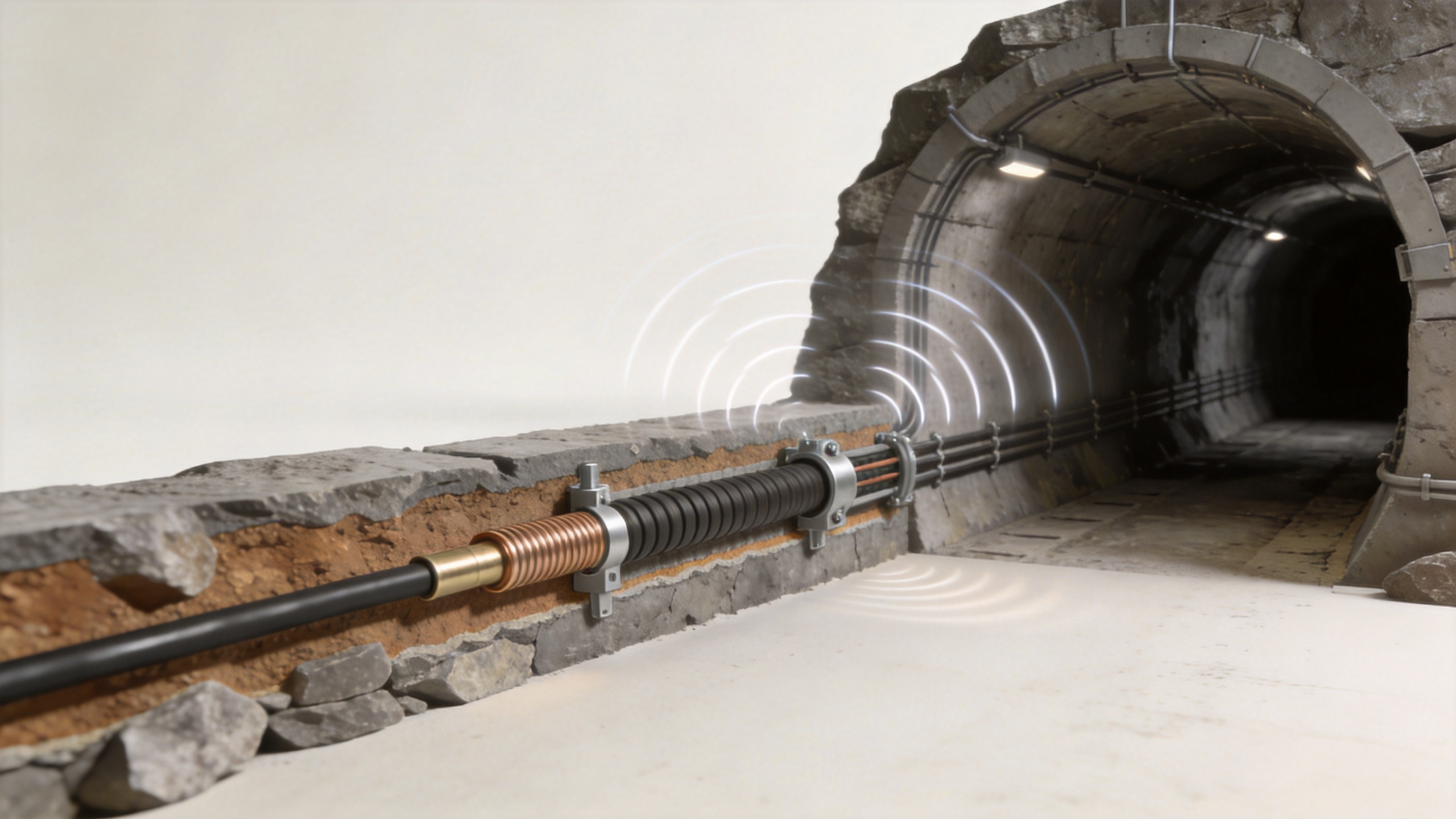
Think of a leaky feeder as a distributed antenna stretched along the full length of a tunnel or mine gallery. Unlike a standard coaxial feeder cable — which is engineered to keep every signal inside its shielded conductor — a leaky feeder cable is intentionally manufactured with periodic slots or apertures in its outer conductor. These controlled openings allow radio energy to "leak" outward along the cable's entire run, creating a continuous ribbon of wireless coverage that follows the tunnel geometry rather than fighting it.
It is not simply a degraded version of a normal coaxial cable. It is a precision-designed radiating transmission line. ITU-R Recommendation M.1075 formally defines it as "a form of transmission line that enables radiocommunication to take place with or between mobile sets in its vicinity through its leakage." That definition is the technical foundation for every deployment specification that follows.
System Architecture: The Four Core Components
A deployed leaky feeder communication system consists of four functional layers working as a single coverage chain:
- Surface or shaft base station: The origin point of the RF signal. This connects the underground network to above-ground communication infrastructure, dispatch systems, and emergency contact channels. In larger installations, multiple base stations feed into a single underground cable network.
- Signal amplifiers (repeaters/boosters): Because leaky feeder cable loses signal continuously along its length — through both the controlled leakage and inherent cable attenuation — amplifiers are placed at regular intervals, typically every 200 to 500 meters depending on cable size and operating frequency. Their placement is calculated from a link budget, not estimated informally.
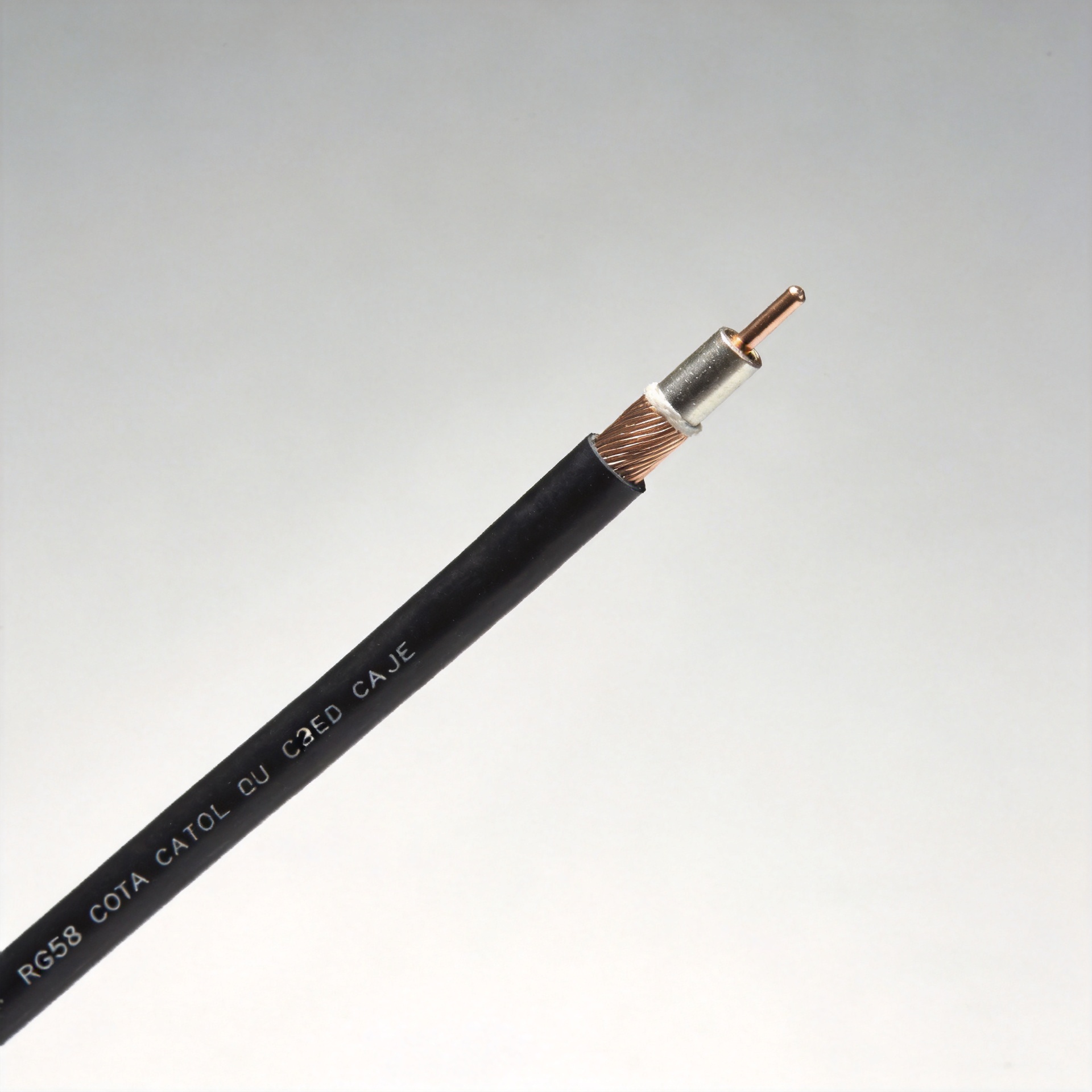
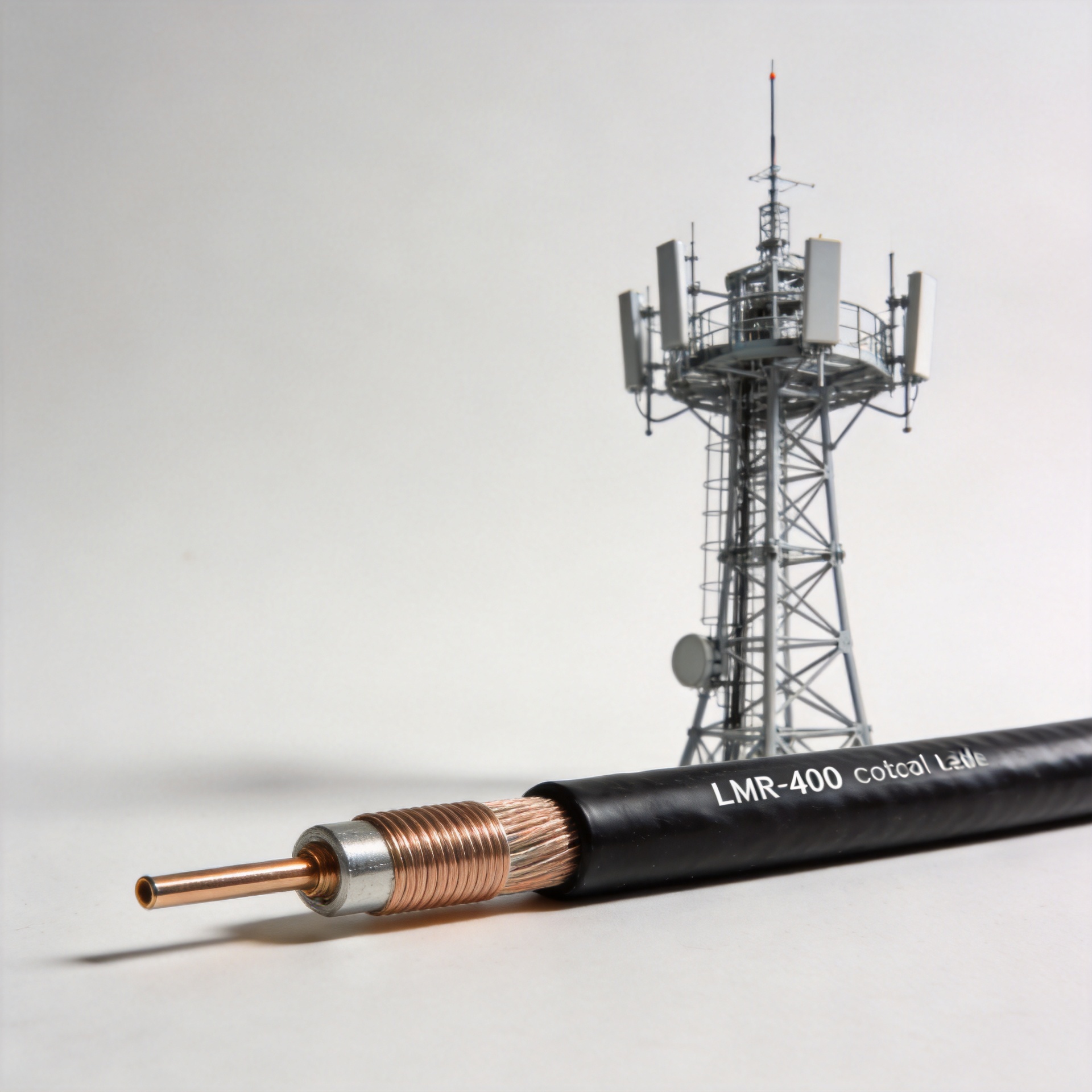
- Leaky coaxial cable: The physical radiating element that runs the length of the tunnel or mine drive. Cable diameter directly affects both attenuation rate and coverage radius. Larger-diameter cables (such as 7/8-inch radiating types) deliver lower loss per 100 meters, supporting longer runs between amplifiers. Smaller-diameter cables (1/2-inch types) are used where flexibility or tight routing geometry is required. Impedance tolerance must be maintained within specification to avoid signal reflections at each connector interface — a detail that shows up as coverage gaps in the field rather than on paper.
- Terminal devices (handheld radios, data modems, sensors): The personnel-carried or vehicle-mounted equipment that communicates with the system. The cable's signal radiation radius — typically 15 to 50 meters transverse to the cable — determines whether a worker moving through an adjacent crosscut remains within coverage.
Frequency Compatibility: TETRA, LTE, and WiFi
The operating frequency of a leaky feeder network is not arbitrary. Leaky feeder cables are typically designed for frequencies under 1 GHz, where signal attenuation per 100 meters remains manageable across long tunnel runs. That physical constraint directly determines which radio technologies are practical:
- TETRA (380–400 MHz, 450–470 MHz): The dominant technology for underground mine voice communication in most regulated markets. TETRA's frequency range produces low cable attenuation, reliable signal reach into side galleries, and compliance with public safety communication frameworks. Tunnel radio leaky feeder installations in major mining operations globally are predominantly TETRA-based.
- LTE (700/800 MHz band): Used where data throughput requirements — for video monitoring, sensor telemetry, or remote equipment control — exceed TETRA's voice-centric capacity. The 700–800 MHz band keeps attenuation within usable limits for leaky feeder deployment, though link budgets are tighter than TETRA.
- WiFi (2.4 GHz / 5 GHz): Conditionally viable in shorter runs — subway platform sections, building utility corridors, or mine headings under 200 meters. At 2.4 GHz, cable attenuation roughly doubles compared to 400 MHz, which compresses amplifier spacing and increases infrastructure cost. For extended underground tunnels, 5 GHz WiFi is generally impractical without dense amplifier placement.
The correct conclusion is not that one frequency band is universally superior. The cable specification must be matched to the frequency, the tunnel length, the required coverage radius, and the regulatory framework — none of these variables exist in isolation.
Regulatory Requirements and Safety Standards
Underground communication coverage is not optional in most regulated mining jurisdictions. In the United States, MSHA (Mine Safety and Health Administration) requires manufacturers to obtain appropriate MSHA approvals for communication systems used in gassy underground mines, under 30 C.F.R. This means the cable, amplifiers, and terminal equipment all enter a compliance chain — a failure at the cable specification level can invalidate the entire system approval.
Similar mandatory frameworks exist in Australia (under the relevant state mining acts), the European Union (ATEX/IECEx certification for equipment in explosive atmospheres), and in major coal and metal mining jurisdictions in Asia and South America. The design point for a compliant leaky feeder communication system is not what minimally functions — it is what satisfies the applicable regulatory approval at the lowest lifecycle cost.
Why Leaky Feeder Cable Specification Is the Starting Point
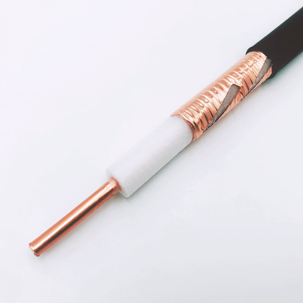
System integrators and mine operators often focus first on the base station or radio terminal specification. The cable is the component that determines whether the rest of the system performs as modeled. Impedance tolerance, outer conductor mechanical integrity under repeated bending, and the consistency of slot geometry along the cable length all directly affect coverage uniformity.
For procurement teams sourcing leaky feeder cable for tunnel or mine deployments, Zhenjiang Jiewei Electronic Technology Co., Ltd manufactures a range of radiating coaxial cables designed for these environments, including the HLCAY(R)-50-12 1/2-inch radiation type leaky feeder cable, the HLCTY(R)-50-22 7/8-inch radiation type leaky feeder cable, and the 75 Ohm SLYWV tunnel and mine communication leaky feeder cable, with 25 years of focused RF interconnect manufacturing experience and export documentation for international procurement.
The leaky feeder cable is not the most visible component of an underground communication system. It is, however, the one that runs the full length of the mine and the one that cannot be easily replaced once the tunnel is operational. Specifying it correctly from the start is the engineering decision that the rest of the system depends on.