EN
EN

What Is LMR400 Coaxial Cable? Specifications, Loss, and Typical Use Cases
If you have spent any time specifying feeder cables for telecom infrastructure or RF test setups, you have probably encountered the designation LMR 400 more than once. But what actually defines this cable, and how does it behave once you move from the datasheet to a real installation? This piece lays out the key specifications, insertion loss figures, and the practical scenarios where LMR400 cable is — and is not — the right choice.
Construction and Core Characteristics of LMR400 Cable
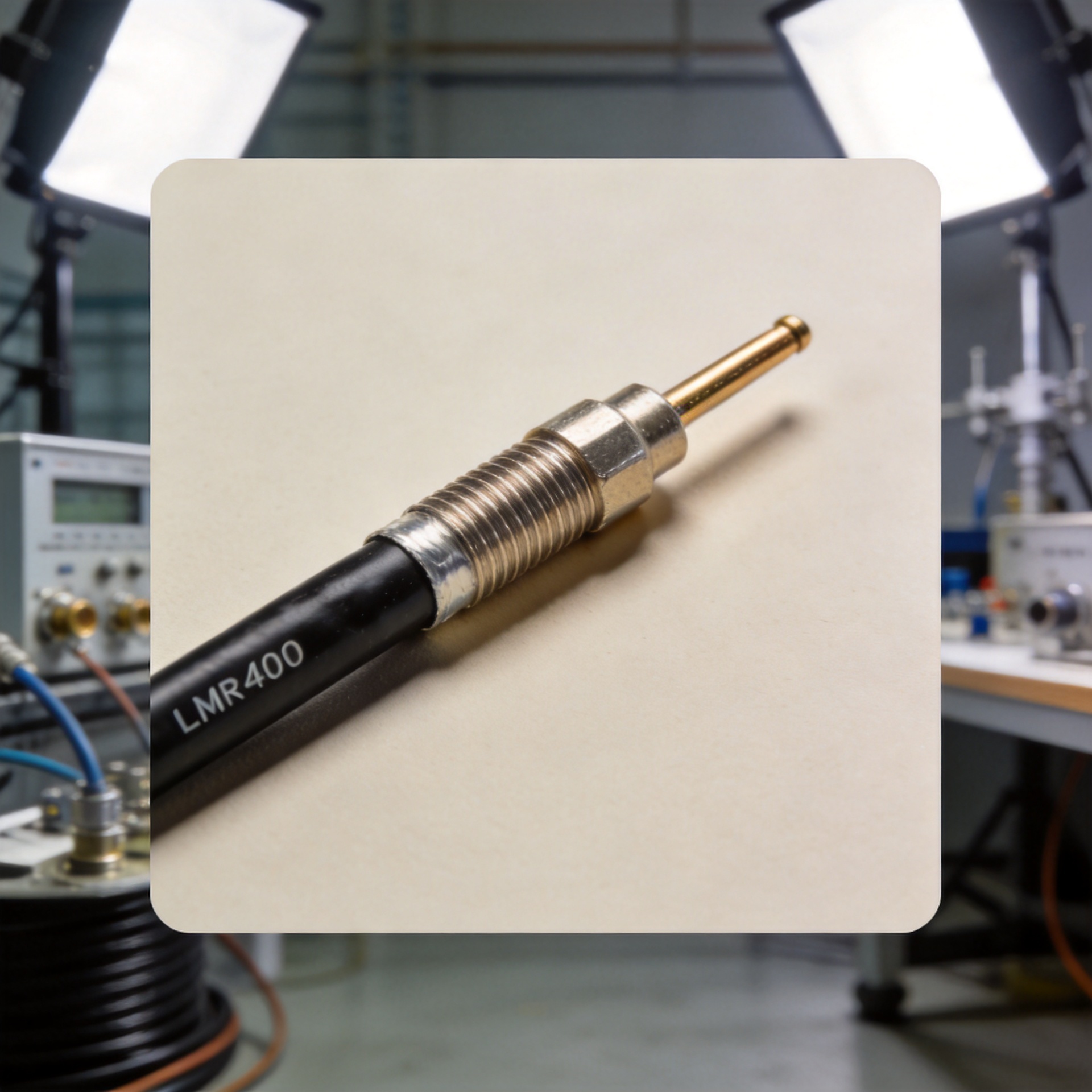
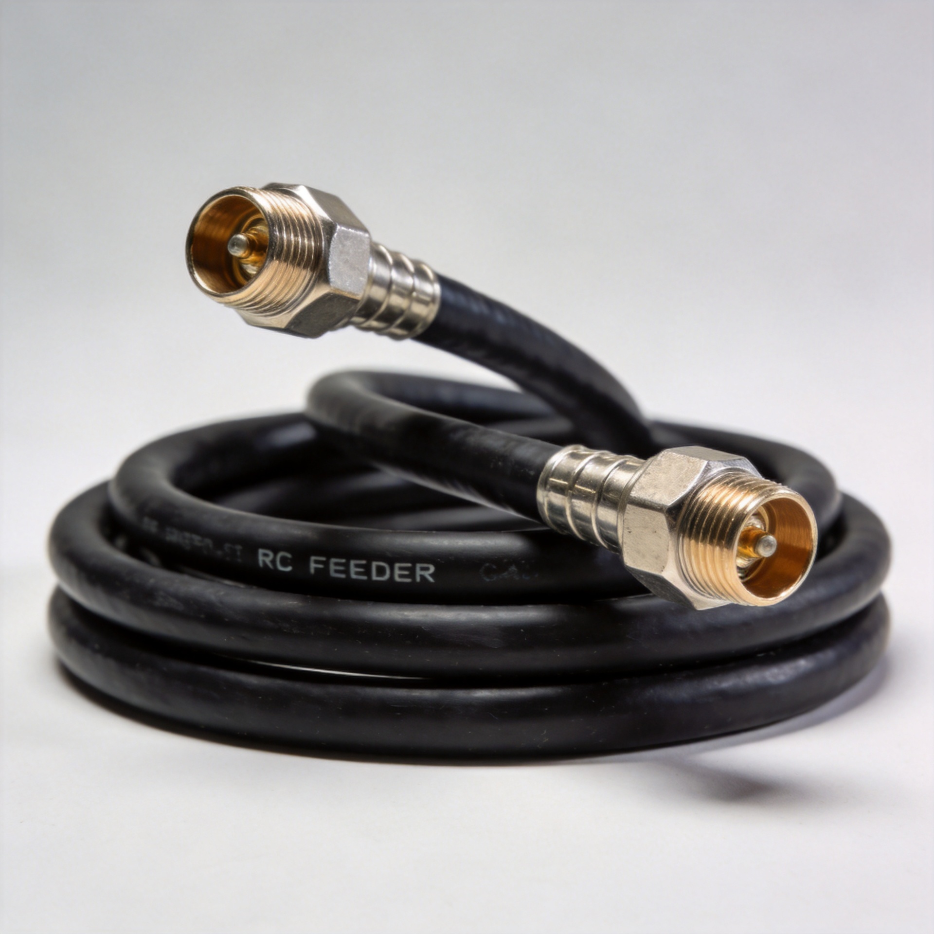
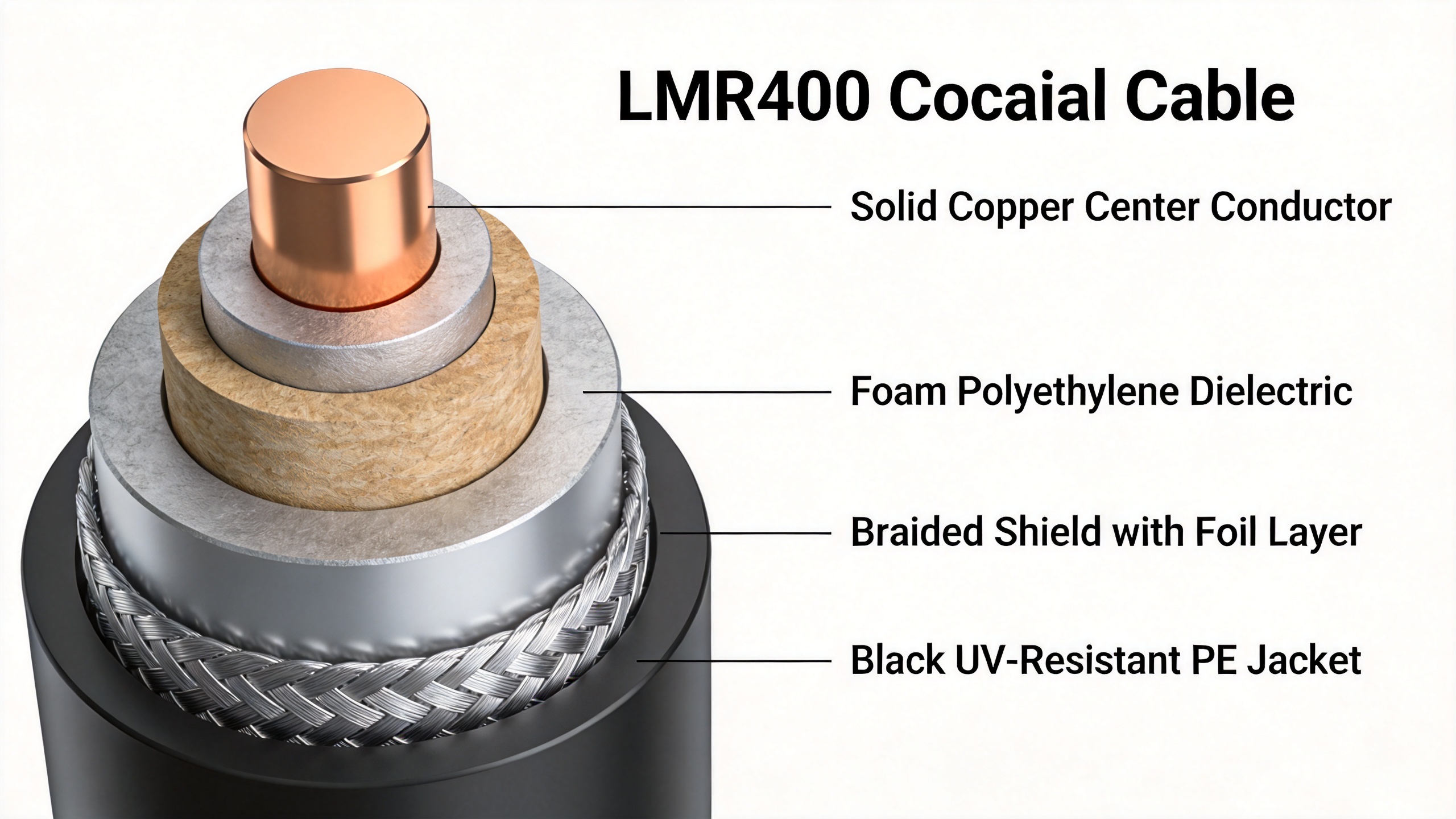
Before comparing numbers, it helps to understand what lmr 400 is — and what it is not. LMR400 is not a rigid semi-rigid hardline and not a corrugated copper trunk cable. It is a flexible, low-loss 50-ohm coaxial cable originally developed as a higher-performance replacement for legacy RG-8/U and 9913-type cables. The construction stacks up as follows:
- Center conductor: Solid bare copper or copper-clad aluminum (CCA), approximately 0.108 inches (2.74 mm) in diameter
- Dielectric: Foam polyethylene — lower loss than solid PE and a key driver of the cable's low attenuation
- Shielding: A bonded foil layer plus a high-density braided outer shield (typically 95–98% coverage) for consistent impedance control along the entire run
- Jacket: Black UV-resistant polyethylene rated for both indoor and outdoor installation, with a maximum operating temperature of 85°C
Overall outer diameter is 0.405 inches (10.3 mm). The cable maintains 50-ohm impedance throughout its length, making it compatible with the vast majority of RF connectors and system ports used in telecom, DAS, and measurement equipment.
Insertion Loss: Reading the Numbers in Context
The headline figure for LMR 400 is its low insertion loss. Measured values from multiple sources converge around approximately 4.1–4.25 dB per 100 feet (roughly 13–14 dB per 100 meters) at 1 GHz. At 5.8 GHz, that figure climbs to approximately 10.8 dB per 100 feet. Think of insertion loss as the tax your signal pays per unit length of cable — and LMR400 is among the lowest-tax flexible cables in its diameter class.
Low insertion loss does not guarantee good system performance on its own — that is a distinction that matters in practice. A 10-meter lmr 400 cable run introduces roughly 1.4 dB of loss at 1 GHz — acceptable for most jumper and feeder applications — but that budget disappears quickly if connector terminations are imprecise or weatherproofing degrades over time. The datasheet value reflects a pristine, correctly terminated cable under lab conditions. Field performance depends on what you put on the ends and how well those connections are maintained.
Velocity of propagation runs approximately 85%, and the minimum installation bend radius is 4 inches (10 cm). Both figures matter in practice: the bend radius determines how the cable can be routed in a confined equipment cabinet or tower mounting bracket, and the VOP value affects electrical length calculations when designing timed delay lines or phase-matched pairs.
LMR400 vs. 1/2-Inch Flexible Feeder: Flexibility and Weight Trade-offs
One recurrent question in RF infrastructure design is whether to use LMR 400 or a 1/2-inch low-loss flexible feeder (such as cables conforming to the LDF4-50A or LCF12-50J interface standard). The 1/2-inch class offers lower insertion loss per meter — roughly half the loss of LMR400 at the same frequency — because the larger diameter reduces conductor resistance and dielectric losses.
However, the trade-off is weight and handling. A 1/2-inch flexible feeder is heavier and has a larger minimum bend radius, which makes it less practical for short jumper runs, tight-corner routing inside a base station cabinet, or mobile measurement setups. LMR400, being lighter and genuinely flexible, is better suited to applications where the cable will be connected, disconnected, and re-routed periodically, or where installation geometry imposes sharp bends.
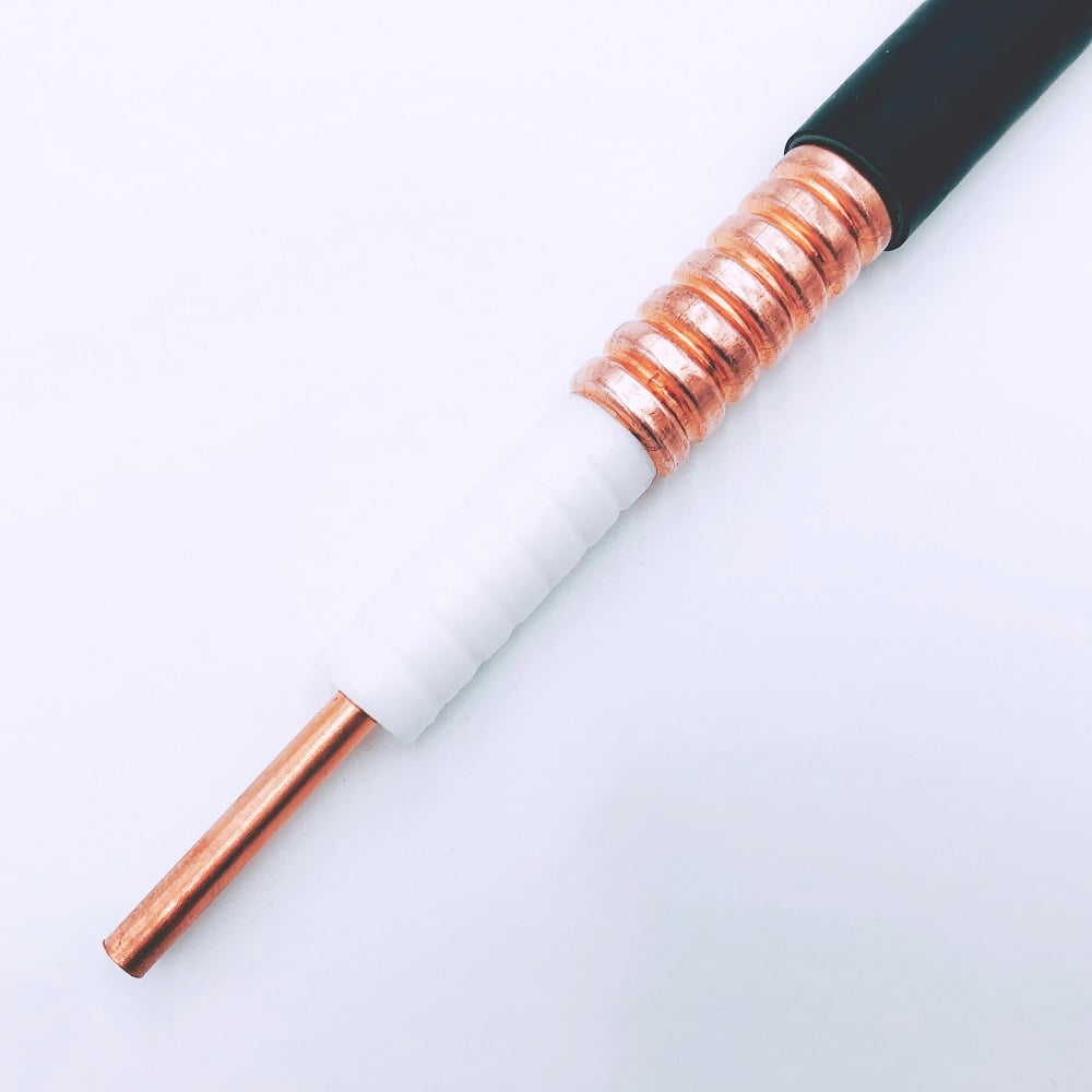
If your application involves a long trunk run — say, from the base of a tower to an antenna port 30 meters up — the lower loss of a 1/2-inch cable such as the HCAAY(Z)-50-12 1/2" Low Loss Flexible Cable with Flame Retardant Halogen Free Jacket is worth the added stiffness. For short jumper connections between a radio unit and an antenna port, or for portable test equipment, LMR400 cable provides enough performance with far better handleability.
Typical Use Cases for LMR400
The specification profile maps directly to where this cable fits in practice:
- Base station jumper cables: The short flexible runs — typically under 3 meters — that connect a radio module to the main feeder or to an in-building antenna port. The 4-inch bend radius makes routing in crowded rack environments straightforward.
- DAS feeder segments: In distributed antenna systems, lmr 400 handles the horizontal feeder runs between a splitter/combiner unit and individual passive antenna elements, particularly where run lengths stay below 15–20 meters. Longer trunk runs in a DAS typically justify moving up to 1/2-inch hardline.
- Antenna test and measurement cables: R&D labs and field calibration teams value LMR400 for its consistent electrical behavior, flexibility during repeated connection cycles, and compatibility with standard N, TNC, and SMA terminations. The cable holds its loss characteristic well across the 300 MHz to 3 GHz range that covers most current cellular and WLAN test work.
- Outdoor infrastructure backhaul jumpers: The UV-resistant PE jacket makes this cable suitable for outdoor exposure on rooftop installations and tower transitions, as long as appropriate weatherproofing is applied at each connector interface.
Practical Selection Guidance
For runs under 15 meters at frequencies below 3 GHz, LMR 400 is typically sufficient for both performance and cost. If your run extends to 30 meters or longer, or if you are working at 5 GHz and above, quantify the total path loss budget before committing to this cable — the 10.8 dB per 100 feet at 5.8 GHz adds up quickly on longer runs. And while LMR400 handles higher frequencies reasonably well, choosing this cable primarily because it is rated to 5.8 GHz does not automatically make it the right choice for every high-frequency deployment. Match the cable's loss figure to the link budget before ordering.
Zhenjiang Jiewei Electronic Technology Co., Ltd. has manufactured RF feeder cables and cable assemblies for over 25 years, serving telecom operators, system integrators, and test equipment builders across Asia, Europe, and North America. Whether you are specifying lmr 400 cable for a DAS project, evaluating 1/2-inch flexible feeders for a tower installation, or sourcing custom-length assemblies with specific connector combinations, the Jiewei technical team can provide product data and sample arrangements for your evaluation.