EN
EN

RF Cable Assembly Manufacturing Process: From Design to Delivery
When procurement teams evaluate an OEM supplier for RF cable assemblies, understanding what happens inside the production floor matters as much as reading a spec sheet. A wire harness assembly for RF applications involves a sequence of tightly controlled steps. Each one affects the electrical performance that downstream systems depend on. This overview walks through the complete manufacturing process, from initial design review to final shipment, so you know what quality control to expect at every stage.
Stage 1: Design Review and Specification Confirmation
Every RF cable and harness assembly order starts with a review of the customer's drawing, BOM, connector pinout, impedance requirements, and test conditions. At this stage, the manufacturing team confirms whether the specified connector series, cable type, and bend radius are mutually compatible. For RF assemblies, impedance discontinuities translate directly into return loss, so this review is not a formality. Dimensional mismatches between connector interface and cable outer diameter cause measurable degradation that no downstream repair can fully correct.
DFM review catches specification issues before production: atypical crimp tool requirements, insufficient strain relief length, and label placement that would be obscured after bundling. Resolving these details before material ordering prevents costly mid-run changes and protects the integrity of the final wire harness assembly.
Stage 2: Material Preparation and Incoming Inspection
Approved connectors, coaxial cables, heat shrink tubing, and protective accessories are pulled from qualified inventory. For RF assemblies, incoming inspection is more rigorous than for standard harness cable assembly work: connectors are checked for plating integrity, mating dimension compliance, and center contact straightness. Coaxial cable reels are verified against impedance specification, dielectric diameter, and shielding coverage percentage.
Any substitution, including a nominally equivalent part from a different batch, triggers a re-qualification check. When evaluating suppliers, ask whether the facility maintains approved vendor lists (AVLs) and how non-conforming material is quarantined. This is one of the questions buyers often wish they had asked earlier in the sourcing process.
Stage 3: Cable Cutting and Stripping
Cables are cut to drawing-specified length using manual or automated cutting equipment. Coaxial cable stripping removes successive layers (outer jacket, braid shield, dielectric, and inner jacket) to expose each conductor layer at precise depths. Strip length tolerances are typically held within ±0.3 mm; nicked strands compromise both electrical continuity and long-term fatigue resistance at the termination point.
For braided shield types, the braid is folded back uniformly before connector installation. Foil-shielded cables require careful drain wire management to maintain 360-degree shield continuity, a detail that directly affects the shielding effectiveness of the finished cable and harness assembly.
Stage 4: Connector Termination – Crimping and Soldering
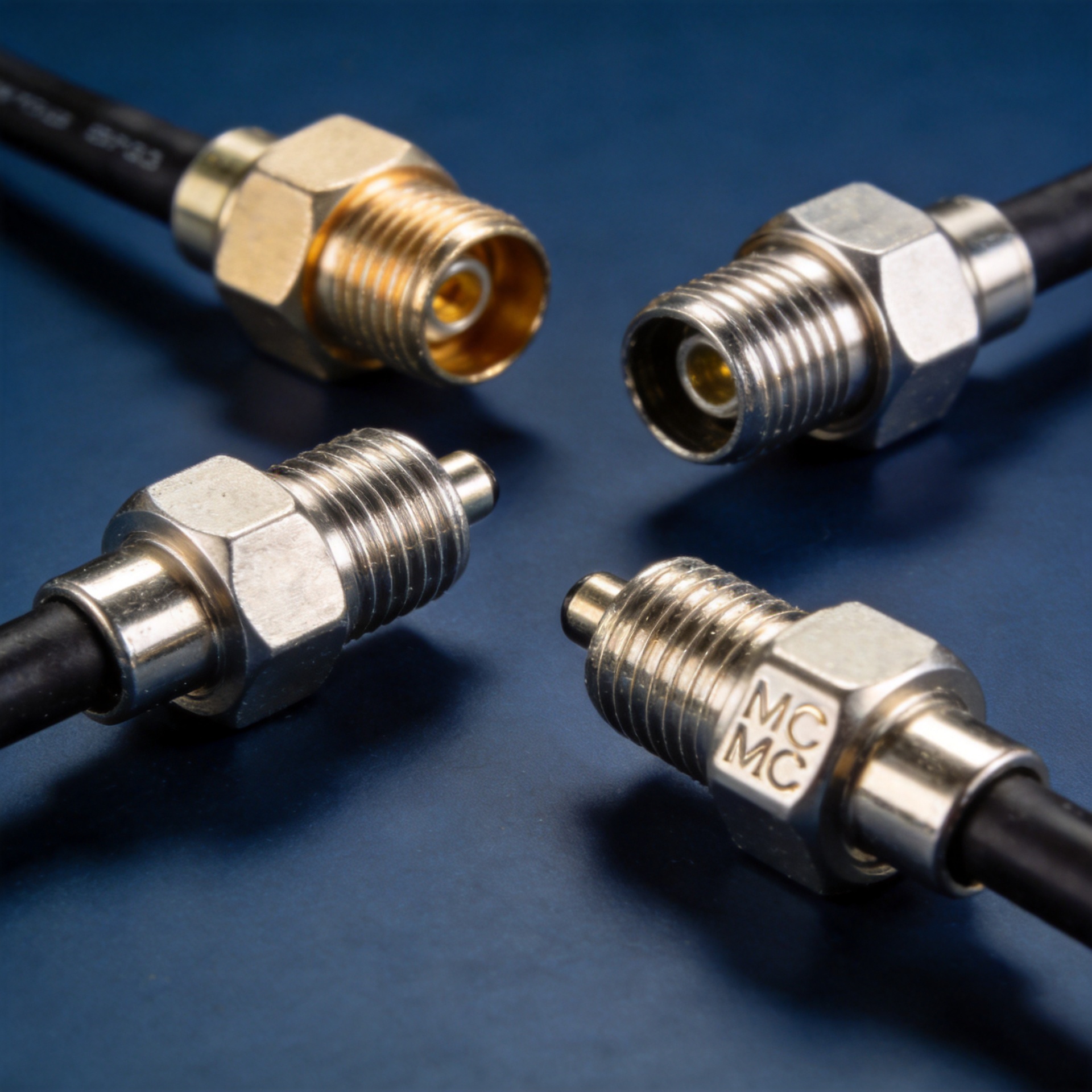
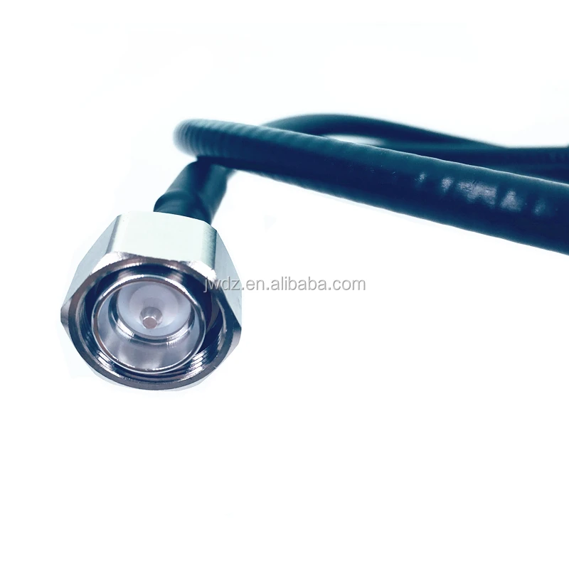
RF connector termination method depends on connector type. Crimp-style connectors, including 4.3-10 series interfaces used in distributed antenna systems and 5G base station feeder runs, use controlled crimp tooling to attach the connector body to the cable's outer braid. Crimp height is measured on every production lot; pull-force testing confirms the mechanical bond meets the connector manufacturer's minimum specification. These controlled process steps are what separate a reliable production wire harness assembly from one assembled with uncertified tooling.
Solder-style connectors require controlled iron temperature and minimal dwell time to avoid heat migration into the dielectric. Impedance discontinuities introduced by voids or cold solder joints are detectable during electrical testing, but prevention through process discipline is less expensive than rework.
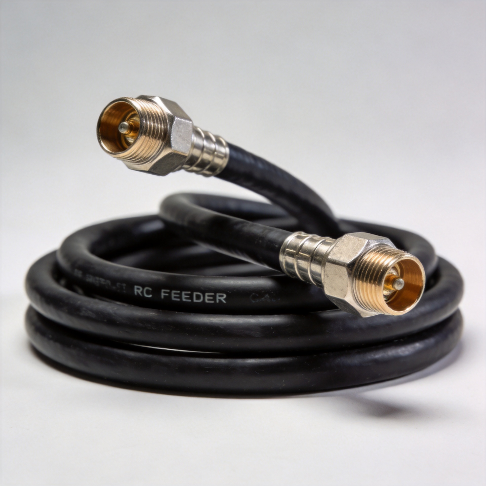
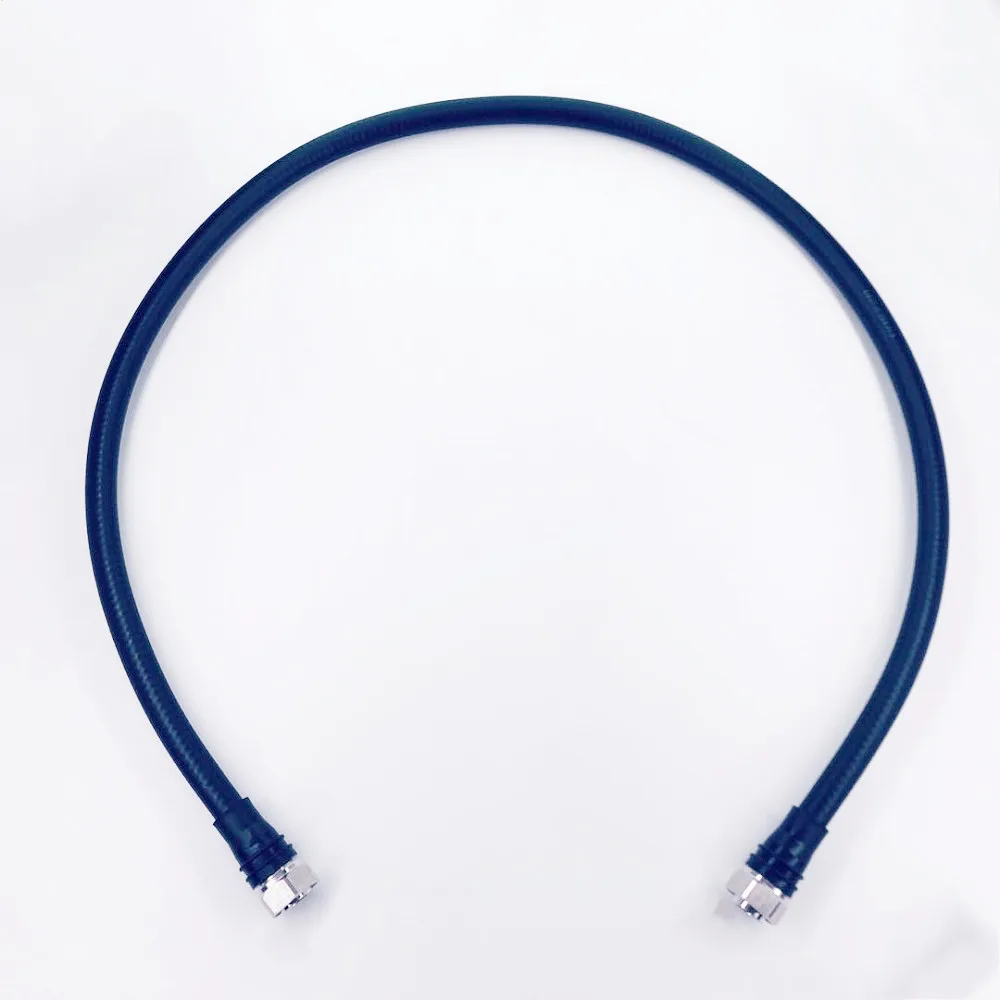
For reference, production-ready configurations from Zhenjiang Jiewei include 1/2 super flexible cable assemblies with 4.3-10 male-to-male interfaces and low PIM 5G cable assemblies with MINI DIN 4.3-10 terminations for 1/4 cable, both built to the same crimp and solder process standards described here.
Stage 5: Assembly, Routing, and Protection
With connectors terminated, assemblies move to a harness board or fixture. Branch length, connector orientation, and routing are set at this stage. For multi-port assemblies, dimensional consistency here directly affects installation fit at the cabinet or antenna end.
Protective materials are applied per drawing: corrugated conduit, braided sleeving, heat shrink tubing, cable ties, and connector boots. Weather-seal accessories provide ingress protection for outdoor antenna applications. Labeling at this stage adds part number, serial number, and date code for downstream traceability throughout the assembly's service life.
Stage 6: RF Electrical Testing and Quality Verification
Every completed RF harness cable assembly undergoes electrical verification before shipment. For coaxial assemblies, the standard measurement set includes:
- Insertion loss: Power lost through the assembly at operating frequencies, measured across the specified range.
- VSWR / return loss: Reflection coefficient at each connector interface, indicating impedance match quality.
- Continuity and short-circuit test: Pin-to-pin map verification for all signal paths.
- PIM (Passive Intermodulation): Required for assemblies used in multi-carrier base station environments where intermodulation interference directly reduces network capacity.
Test fixtures are calibrated to connector reference planes; results are logged to production records per assembly lot. Assemblies that fail insertion loss or PIM thresholds return for root-cause analysis: commonly a connector seat gap, marginal solder joint, or contamination at the mating interface.
Final Inspection, Documentation, and Packaging
Visual inspection checks connector condition, label legibility, heat shrink coverage, and overall conformance to drawing. Dimensional checks (finished cable length and connector torque marks) are sampled per lot. Documentation packages include test records, material certificates, and inspection reports per the purchase order terms.
Connectors ship with plastic end caps on all RF interfaces. Anti-static bags cover shielded assemblies, and carton cushioning is selected based on connector series fragility.
What to Ask Your RF Cable Assembly OEM
With 25 years of focused manufacturing experience in RF connectors, feeder cables, and cable assemblies, Zhenjiang Jiewei serves global telecom, broadcast, and 5G infrastructure customers who need wire harness assembly production built on documented process controls. Before awarding volume orders to any RF cable assembly OEM, consider these questions:
- How are crimp height and pull-force data logged, and is that data available per production lot?
- What PIM performance level is specified and tested to, and is PIM verified on 100% of assemblies or sampled by lot?
- Can the factory provide DFM feedback before production begins, and what is the lead time for sample confirmation?
- How are non-conforming materials quarantined, and what is the re-qualification path for substitutions?
Understanding the manufacturing workflow behind a cable and harness assembly quote helps procurement teams compare OEM capabilities on a like-for-like basis: process maturity and quality accountability at each production stage, not just price per piece.