EN
EN

Lightning Surge Arrester vs. SPD: How to Choose RF Surge Protection for Telecom Towers
If you've specified surge protection for base station feeder systems, you've probably run into the same confusion: a supplier quotes you a "lightning surge arrester," another lists it as an "SPD," and the datasheets look almost identical on the surface. What's actually different, and which one belongs in your feedline system?
This isn't a trivial question. Selecting the wrong device—even one that passes initial specification review—can leave an antenna system exposed to the exact transient event it was supposed to survive. That's a lesson most RF engineers learn once and don't repeat.
SPD vs. Lightning Surge Arrester: What the Terms Actually Mean
Let's start with what these aren't: interchangeable terms describing the same thing. In electrical standards, particularly ANSI/UL 1449, the term SPD (surge protection device) replaced older terminology like "secondary surge arrester" and "TVSS" to describe devices that clamp transient overvoltages and protect downstream electronics. A lightning arrester handles the much higher energy transients from indirect lightning events—diverting that energy away from connected equipment and into the ground path.
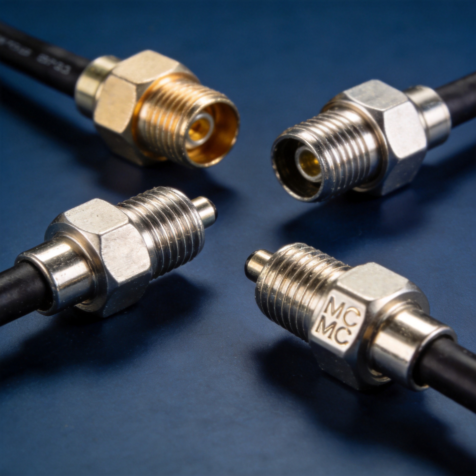
In RF feeder system context, both categories exist as coaxial in-line devices. The distinction shifts toward rated voltage, energy-handling capacity, and the type of transient each device is optimized to handle.
Key Parameters to Compare
When evaluating coaxial surge protection for telecom tower feedlines, the specification comparison should cover at least these dimensions:
| Parameter | Lightning Surge Arrester | RF SPD |
|---|---|---|
| Primary threat | High-energy indirect lightning transients | Conducted surges from switching, nearby strikes |
| Rated DC voltage | Typically 90 V (for standard 4G/5G feeder bias) | Up to 230 V (higher DC power delivery paths) |
| Frequency range | DC – 3.0 GHz (standard); DC – 6 GHz for wider bands | DC – 3.0 GHz or higher depending on design |
| Connector interface | N-type male-to-female (most common for feeder) | N-type male-to-female or application-specific |
| Insertion loss | Typically <0.3 dB across operating band | Similar, verify per datasheet |
| PIM performance | Critical for LTE/5G (specify PIM class) | Varies—verify if PIM-rated for carrier use |
The voltage rating is where most spec-sheet matches fall apart in the field. A device rated for 90 V DC bias will work correctly across a standard Remote Radio Unit (RRU) power feed, but if your system uses higher bias voltage for extended cable runs or multi-carrier configurations, that 90 V device becomes a liability.
Matching the Device to Your Application Scenario
The right choice depends on what you're actually protecting against and where in the feedline system you're installing the device—there is no universal answer that fits every tower configuration.
If your primary concern is indirect lightning energy entering through the feeder cable at the tower top: a gas discharge tube (GDT)-based lightning surge arrester is the right first line of defense. Install it at the tower entry point where the feeder transitions from the outdoor antenna run to the protected equipment room or shelter. The 90 V rated variant is appropriate for most 4G/5G single-carrier feeder applications.
If your application requires a dedicated SPD surge protection device for the DC power feed path rather than the RF carrier path: select a device rated to match your actual bias voltage—90 V or 230 V depending on the system design.
If your system feeds power over the coaxial line (bias tee configurations) at higher voltages: verify that the rated DC voltage matches your actual bias level. Selecting a 90 V device on a 230 V bias path isn't just underspecification—it can cause the device to conduct unnecessarily under normal operating conditions.
If you're protecting high-value LTE or 5G equipment where passive intermodulation (PIM) degrades signal quality: not all surge protection devices are PIM-rated. Confirm that the device carries a published PIM specification, typically expressed as better than –155 dBc at 2 × 20 W (or equivalent to your network's requirements). Installing a standard arrester without PIM verification in a carrier-grade antenna system is the kind of decision that shows up months later as unexplained uplink noise.
Installation Position and Grounding
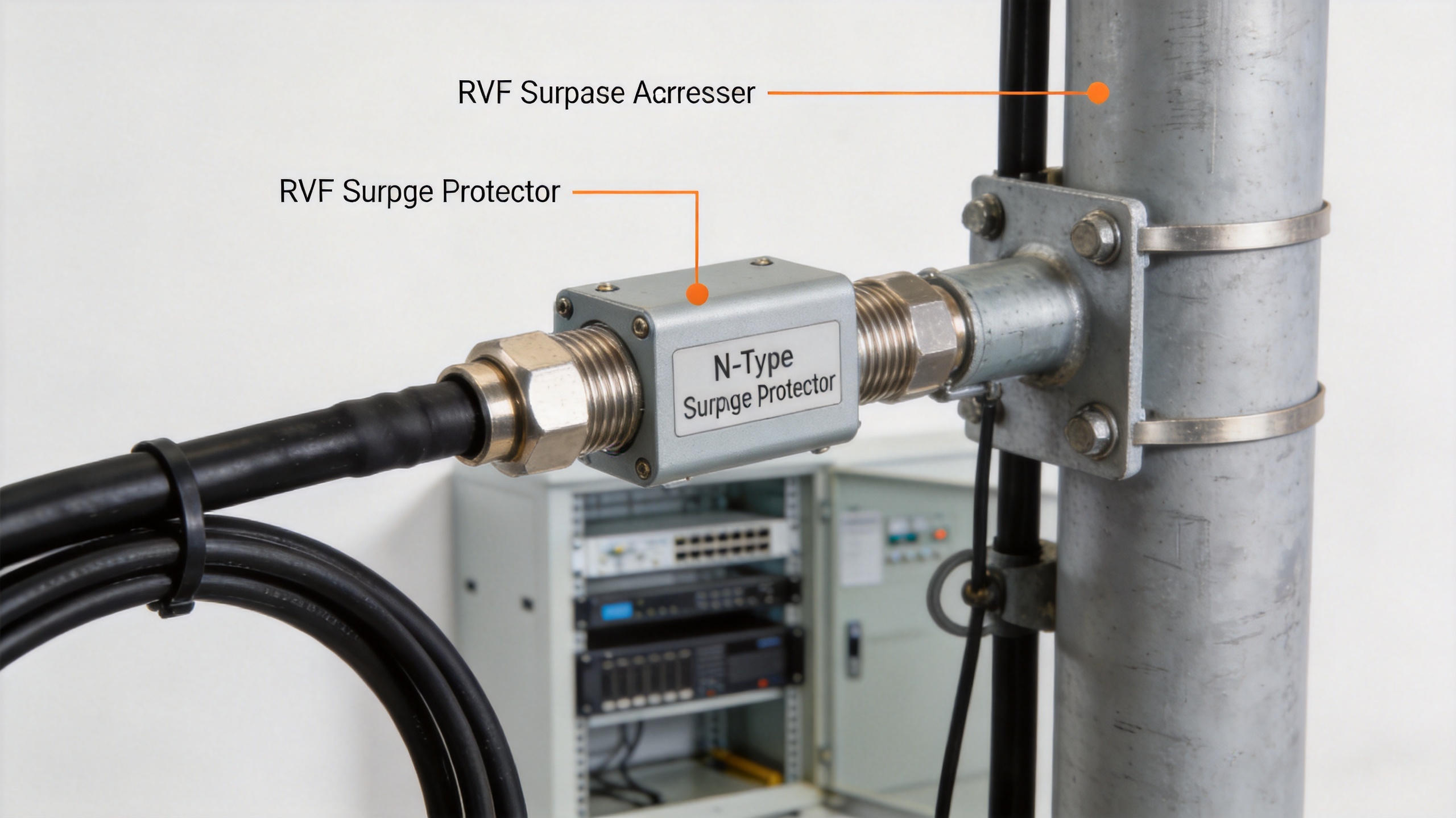
Even a correctly specified device performs poorly if installed incorrectly. The surge arrester needs a direct, low-impedance ground connection—this is not a place to use a shared ground bus with multiple other paths if those paths add inductance. The shorter the ground lead, the more effective the device.
For tower feedline protection, the arrester is typically installed at two points: at the top of the tower immediately behind the antenna, and at the base of the tower where the cable enters the equipment shelter. Two-stage protection is standard practice in high-strike-risk environments. A single device at the shelter entry only addresses conducted energy that has already traveled the full feeder length.
Product Examples for Telecom Tower Feeder Applications
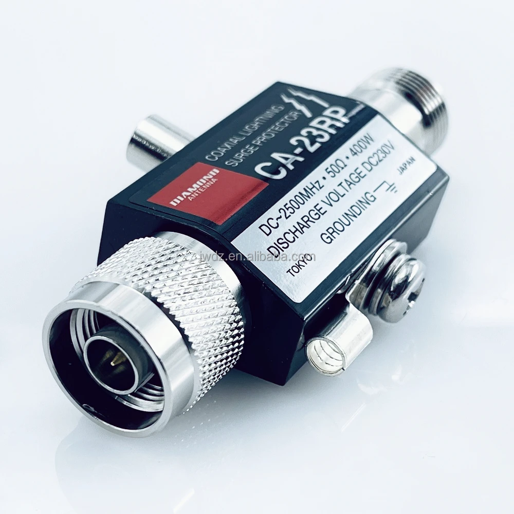
For N-type feeder systems operating from DC to 3.0 GHz, Zhenjiang Jiewei manufactures coaxial surge protectors designed for base station and telecom tower applications. Two representative options:
- N-JKYP-3G Surge Protector DC–3.0 GHz, N Male to N Female Surge Arrester Lightning Protector — a compact in-line arrester for standard feeder applications.
- CA-23RP DC–3.0 GHz N Male to N Female Surge Arrester Lightning Protector — a professional-grade design option for systems where heavier mechanical construction and tighter electrical tolerances are specified.
For applications above 3.0 GHz, or where specific PIM ratings are required, confirm the extended specification with the manufacturer before procurement.
Making the Selection Decision
Before finalizing your spec—whether you're selecting a lightning surge arrester, a passive SPD surge protection device, or a combination of both—run through these four checks:
- What is the actual DC bias voltage on this feeder run? Match the device rated voltage to your system, not to a generic datasheet example.
- What frequency range does your antenna system use? Confirm the arrester operates with acceptable insertion loss across your full band, including any future band additions.
- Is PIM a concern for this installation? If yes, verify the device carries a published PIM rating.
- Where are the installation points? Two-stage protection (tower top + shelter entry) is preferable for exposed high-mast installations.
Aligning on these four parameters upfront is considerably cheaper than the truck roll—and the equipment replacement—that follows when a device fails to handle the event it was selected to prevent.