EN
EN

Cable Overmolding in RF Assemblies: Design Considerations
In an RF interconnect, the molded transition around a connector is not merely a cosmetic finish. Cable overmolding can protect a cable exit, distribute bending loads, and help create a more robust assembly for installation and handling. Yet an RF assembly also has an electrical job to do: it must preserve the impedance-controlled path that the cable and connector were selected to provide. Sound cable overmolding decisions therefore begin with the interface, not with the mold shape alone.
For telecom infrastructure and equipment teams, a custom cable assembly is usually reviewed by engineering, purchasing, installation, and operations. Each group sees a different risk. Engineering looks at return loss, shielding continuity, and the connector transition. Installers need a manageable bend and reliable retention. Procurement needs repeatable requirements that can be checked from one production lot to the next. A useful design review connects all of those needs before tooling is released.
Start with the RF interface and the intended installation
Before choosing a cable overmolding material, define the actual electrical and mechanical interface. Confirm the cable construction, connector family, cable exit direction, intended mating cycle, route geometry, and available clearance around the installed connector. Also document the frequency range, impedance requirement, and any customer-defined limits for VSWR, insertion loss, continuity, or shielding performance. The spec that matters most is the one that exposes a transition problem before the assembly reaches the field.
It is tempting to say the cable loss specification is the whole story. It is not, quite. A short assembly can still be sensitive to how the connector, shield termination, and cable exit are built. Cable overmolding should not conceal an unresolved termination issue. Establish the electrical acceptance plan on representative completed assemblies, then keep the tooling and process conditions controlled enough to reproduce that result.
Design strain relief as a load path, not a rigid sleeve
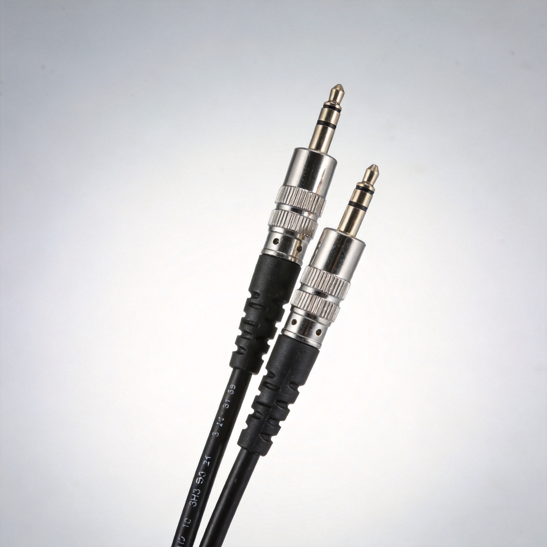
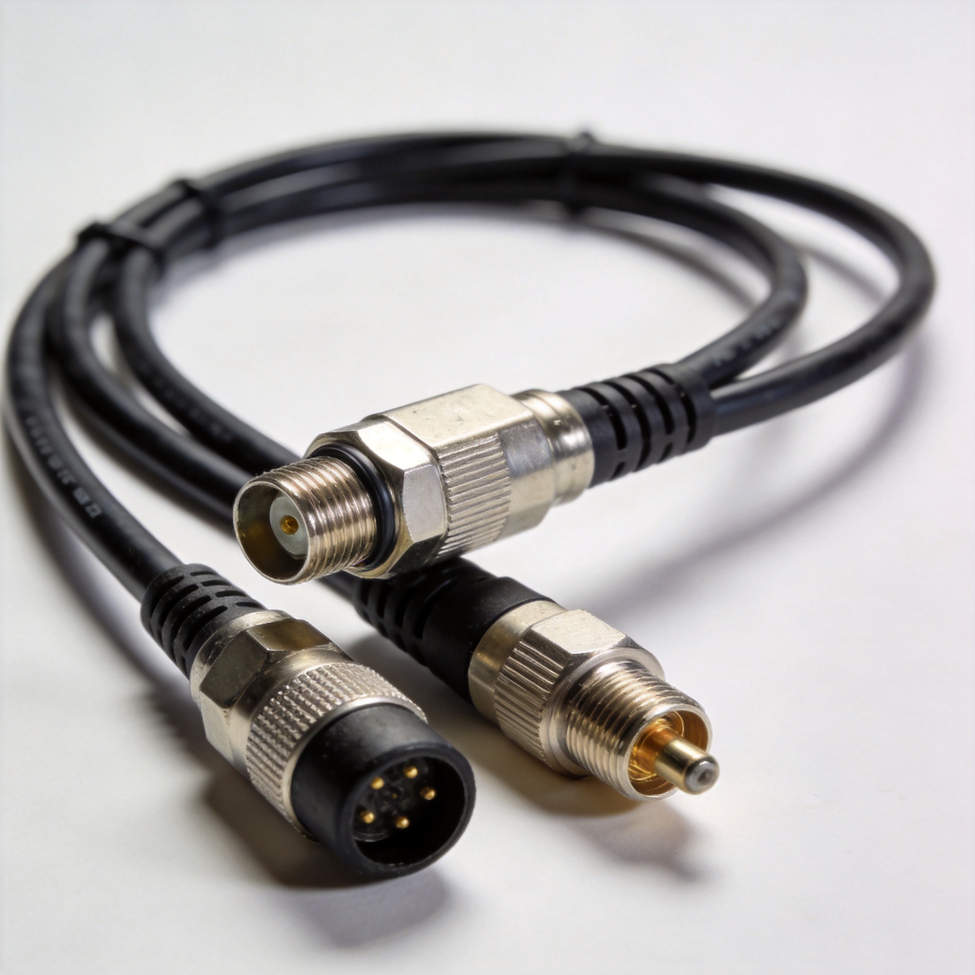
A primary benefit of cable overmolding is strain or bend relief at the connector-to-cable junction. The goal is to move repeated bending away from the most vulnerable termination region. A gradual transition, adequate relief length, and geometry that supports the cable without pinching it are typically more useful than simply adding bulk near the connector.
Ask where installers will grip the assembly, how often the cable will flex, and whether it will be tied down close to the connector. If the assembly is routed in a controlled indoor cabinet, the design may prioritize compactness. If vibration, thermal cycling, moisture, or outdoor exposure is possible, start from the environmental and flexing requirements rather than from appearance or unit price. Material compatibility with the cable jacket and connector surfaces also deserves early review; the molding process should not create a bond, shrinkage effect, or local stress condition that compromises the underlying construction.
Protect shielding and signal integrity during cable overmolding
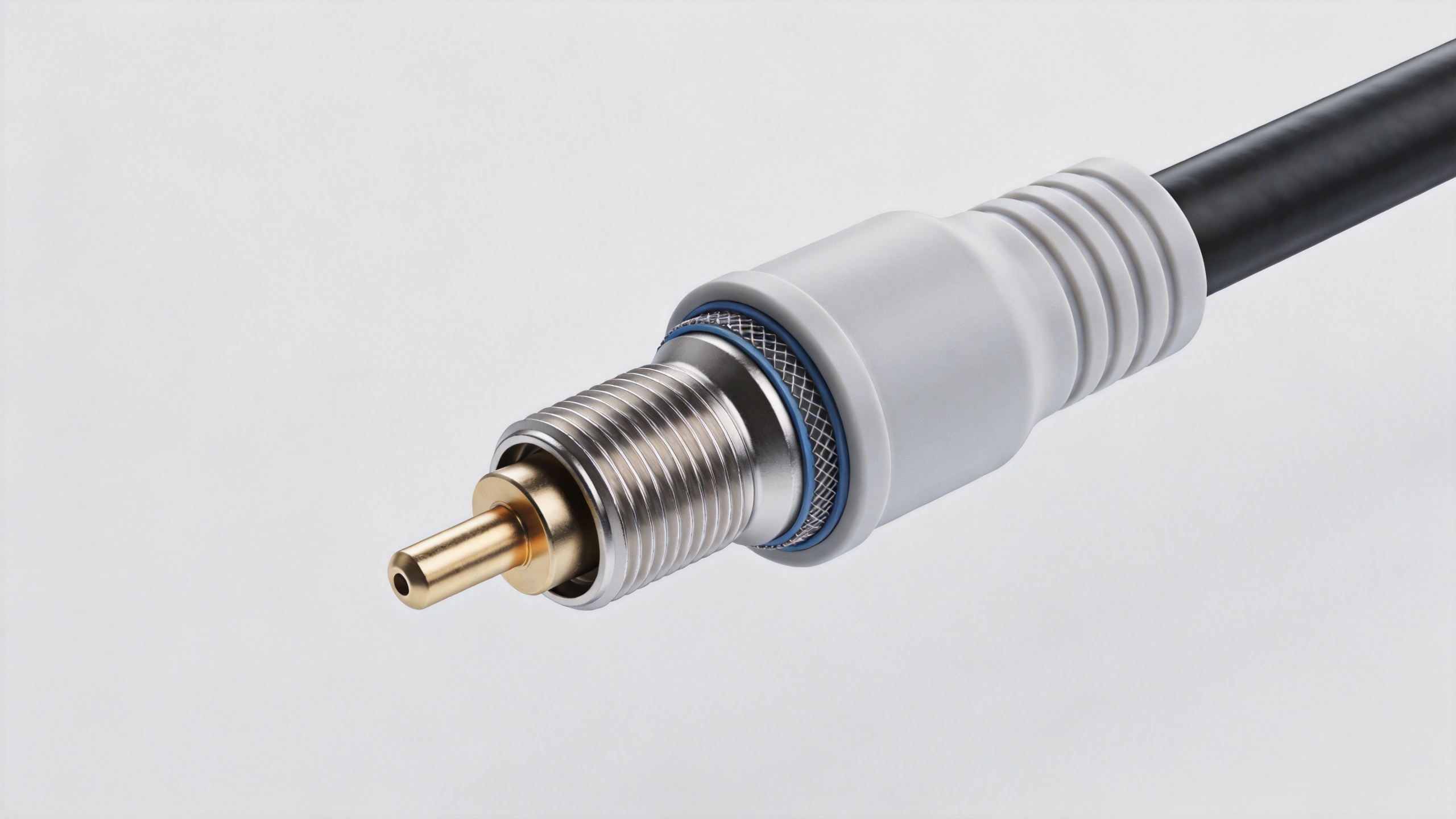
For RF assemblies, cable overmolding must be evaluated together with shield termination and connector construction. The mold and process should avoid displacing braid, stressing dielectric layers, or placing uncontrolled force on the connector interface. Consider whether the overmold needs to accommodate a backshell, grounding feature, or shielding strategy, but do not assume that a polymer overmold itself provides RF shielding.
A practical review sequence is: inspect the prepared cable and connector termination; confirm positional alignment in the mold; define how the cable will be supported during molding; and test the finished assembly against the agreed electrical and mechanical criteria. Where projects require it, compare representative pre- and post-molding RF measurements. This approach helps separate an electrical performance question from a purely cosmetic molding question.
Specify the material and process around the real environment
Cable overmolding material selection should follow the service environment and assembly geometry. Temperature exposure, moisture, UV exposure, chemicals, abrasion, and required flexibility can all change the right choice. The process matters as well: injection molding, low-pressure molding, and other approaches create different thermal and pressure conditions around the cable and connector. Review these conditions against jacket material, sealing needs, and sensitive components before committing to production tooling.
For a custom cable assembly, it is helpful to record material, color, mold parting line, cable orientation, marking needs, and any visual acceptance criteria in the drawing package. This keeps the final part inspectable and reduces interpretation differences between an approved sample and later production. Where the customer uses IPC/WHMA-A-620 or another workmanship framework, align the documented inspection criteria with the applicable project requirements rather than treating a generic molded appearance as proof of acceptance.
Plan assembly controls before approving the tool
Overmolding cannot correct poor preparation. Define the critical process controls for cable strip length, shield handling, connector attachment, orientation, and fixture support. Then define the finished-assembly checks: visual inspection, dimensional verification where relevant, continuity, insulation-related tests where specified, and RF validation when the application requires it. A clear first-article approval should include the finished cable overmolding geometry as well as the electrical result.
One commissioning lesson is worth remembering: an assembly can look finished and still fail when a termination or connector retention detail was not controlled. The cost is not only rework; it can delay installation and complicate root-cause analysis. Building retention and inspection requirements into the cable overmolding plan is usually less disruptive than discovering them after field installation.
Use supplier collaboration to make custom requirements buildable
Custom RF assemblies benefit from sharing the operating context early: application, cable type, connector configuration, routing constraints, target environment, and the test expectations that matter to the buyer. Zhenjiang Jiewei manufactures RF connectors, feeder cables, cable assemblies, and loads, with custom-length assembly capability for installation geometry and connector combinations. When a compatible jumper configuration is relevant to the installation, teams can review the 1/2-inch Super Flexible Jumper Cable 4.3-10 Male to 7/16 DIN Male Cable Assembly alongside the required molded-transition design.
RF cable overmolding checklist
- Define frequency range, impedance, and finished-assembly test expectations.
- Confirm connector, cable, shielding, and exit orientation before tooling.
- Use cable overmolding geometry that distributes bending loads away from the termination.
- Match material and process conditions to jacket compatibility and the service environment.
- Document workmanship, inspection, and first-article acceptance requirements.
- Validate representative finished assemblies, not only individual components.
Well-designed cable overmolding makes an RF assembly easier to handle and better prepared for its environment while respecting the electrical transition underneath. Treat the molded section as an engineered part of the interconnect, and the resulting custom cable assembly will be easier to specify, manufacture, inspect, and deploy.